
Antireflective film, polarizing plate, cover glass, image display device, and method of manufacturing antireflective film

a technology of anti-reflective film and polarizing plate, which is applied in the direction of polarizing elements, instruments, coatings, etc., can solve the problems of insufficient scratch resistance, complex manufacturing process of anti-reflective film, and inability to obtain sufficient hardness, etc., to achieve excellent scratch resistance, low reflectance, and high hardness

Active Publication Date: 2016-03-17
FUJIFILM CORP
View PDF5 Cites 22 Cited by
  • Summary
  • Abstract
  • Description
  • Claims
  • Application Information

AI Technical Summary

Benefits of technology

The present invention provides an antireflective film that has low reflectance, no white turbidity, high hardness, and excellent scratch resistance. The method of manufacturing the antireflective film is simple. The invention also provides a polarizing plate, a cover glass, and an image display device that includes the antireflective film.

Problems solved by technology

However, in JP-A-2009-139796 and JP-A-2011-002759, it is necessary to etch a transparent resin or forming a transparent resin by molding, a manufacturing process for an antireflective film is complicated in some cases.
Also, in JP-A-2011-002759, a hard material is not applicable, and therefore scratch resistance becomes insufficient in some cases.
JP-A-2009-139796 also has a problem that a sufficient hardness cannot be obtained, in addition to the above problem in manufacturing process.
Also, the particles are excessively aggregated, the aggregated portion functions as a scatter so that a film becomes white turbidity and a haze occurs.
As a result, a contrast is deteriorated and a beautiful black tightness of a display due to an antireflective film is impaired.
(2) When a content of particles is low and a content of a binder resin or a binder resin forming compound is high after the coating, the particles are embedded into the binder resin or the binder resin forming compound so that an uneven shape is not formed and sufficient antireflective property is not obtained.
This reason is presumed that after coating the coating liquid, a solvent is volatilized by drying, the low molecular monomer continuously permeates into the substrate or the under layer, and a content ratio of the particles in the coating film becomes relatively high and as a result, aggregation of particles cannot be prevented.

Method used


Image

  • Antireflective film, polarizing plate, cover glass, image display device, and method of manufacturing antireflective film
  • Antireflective film, polarizing plate, cover glass, image display device, and method of manufacturing antireflective film
  • Antireflective film, polarizing plate, cover glass, image display device, and method of manufacturing antireflective film

Examples


example 1

Making of Antireflective Film

[0331]To PET (COSMOSHINE A4100, a product of TOYOBO Co., Ltd.) as a 100 μm-thick substrate, a coating solution of composition for forming antireflective layer A-1 was coated in a wet amount of about 2.8 ml / m2 by a gravure coater, dried at 120° C. for 5 minutes, and then cured by being irradiated with ultraviolet light from an air-cooled metal halide lamp at an irradiation dose of 600 mJ / cm2 as a purge of air with conducting nitrogen so as to achieve an atmosphere with an oxygen concentration lower than 0.1 vol %, thereby preparing an antireflective film A-1. Herein, fine adjustments were made to the wet coating amount and the particle occupancy was measured every time fine adjustment was made. What had the highest particle occupancy was adopted as the antireflective film A-1. An antireflective film A-2 was prepared in the same manner as the antireflective film A-1, except that the substrate was changed from PET to cellulose triacetate film (TG40UL, TAC, ...

example 2

Preparation of Plastic Substrate with Hard Coat Layer

[0358](Preparation of Composition for Forming Hard Coat Layer)

[0359]Into a mixing tank, 10.5 parts by mass of methyl acetate, 10.5 parts by mass of MEK, 22.52 parts by mass of PET, 6.30 parts by mass of urethane monomer (U-4HA) and 0.84 parts by mass of IRUGACURE 184 were charged, stirred and subjected to filtering through a polypropylene filter having a pore diameter of 0.4 μm, thereby preparing a hard coat layer composition B-1 (solid matter concentration of 58 mass %).

[0360]Likewise, a hard coat layer composition B-2 was prepared in the same manner as the hard coat layer composition B-1, except that the proportions of the ingredients were changed so as to make up the composition shown in Table 4. The numerical value pertinent to each ingredient in Table 4 is in parts by mass.

[0361](Preparation of Plastic Substrate with Hard Coat Layer)

[0362]To a cellulose triacetate film (TG40UL, a product of Fujifilm Holdings Corporation), a h...


PUM


Abstract

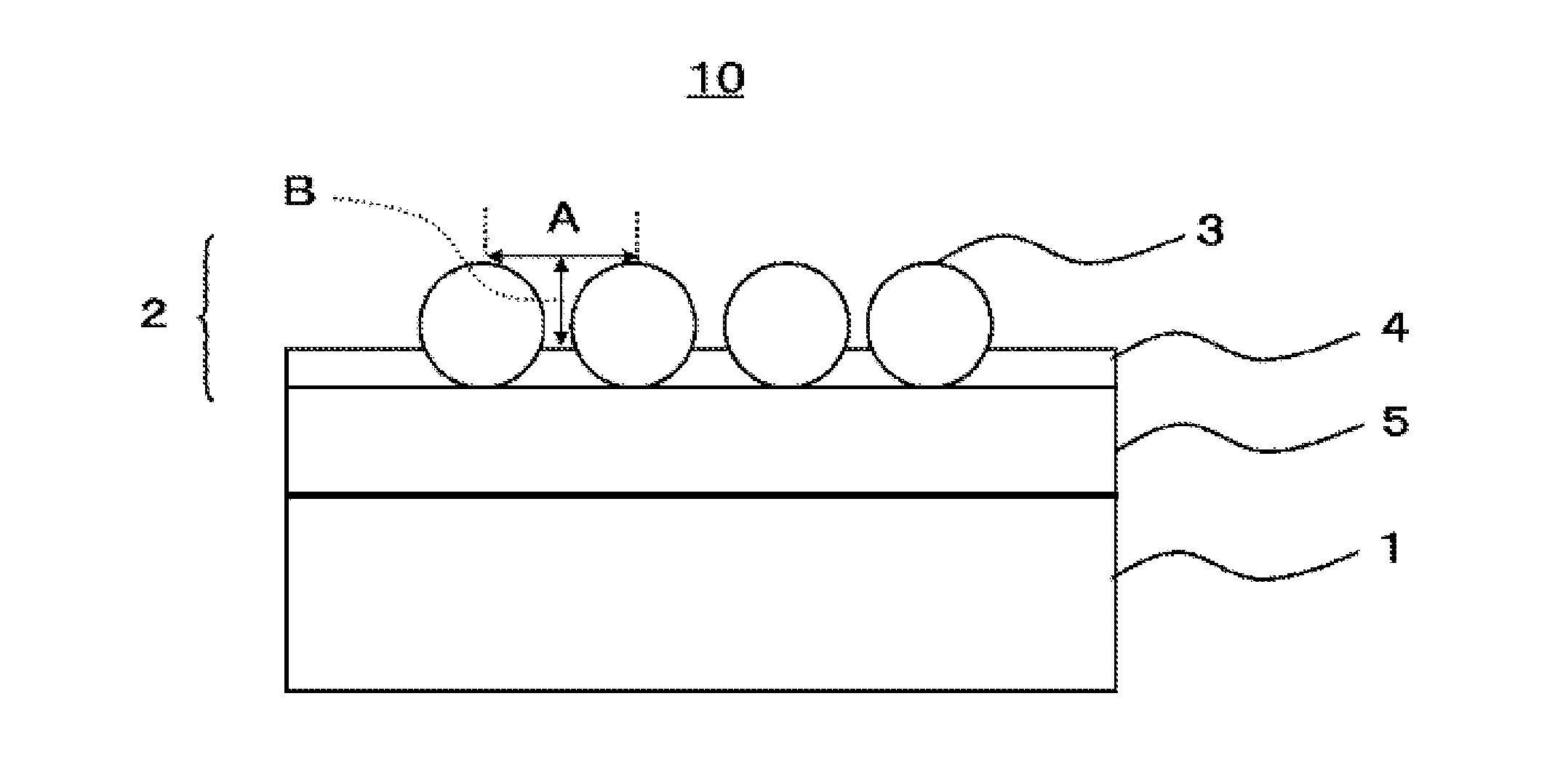
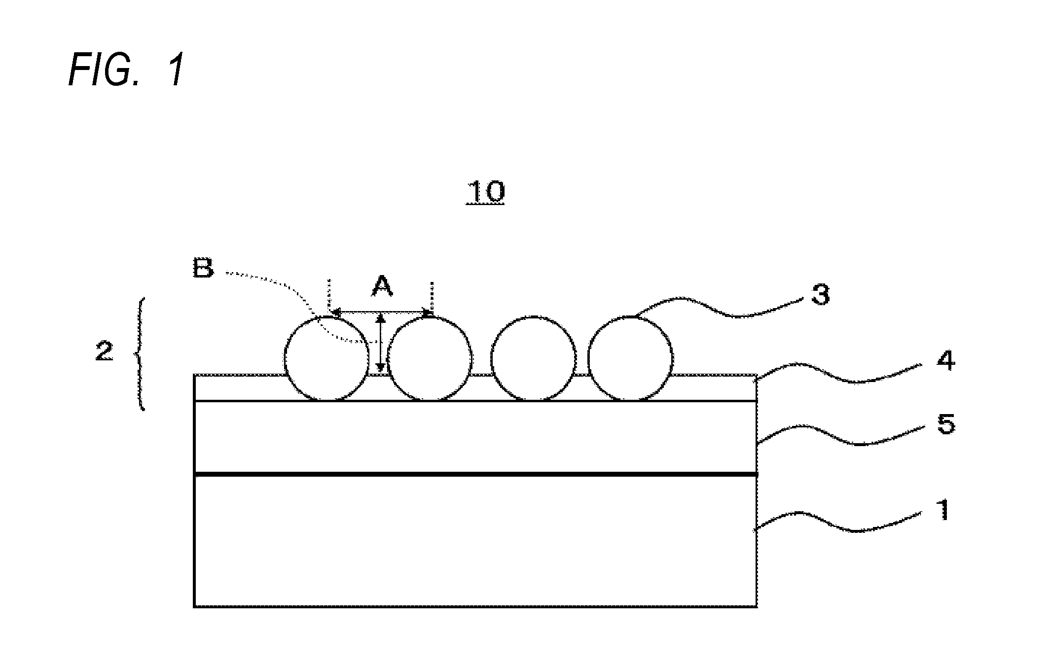
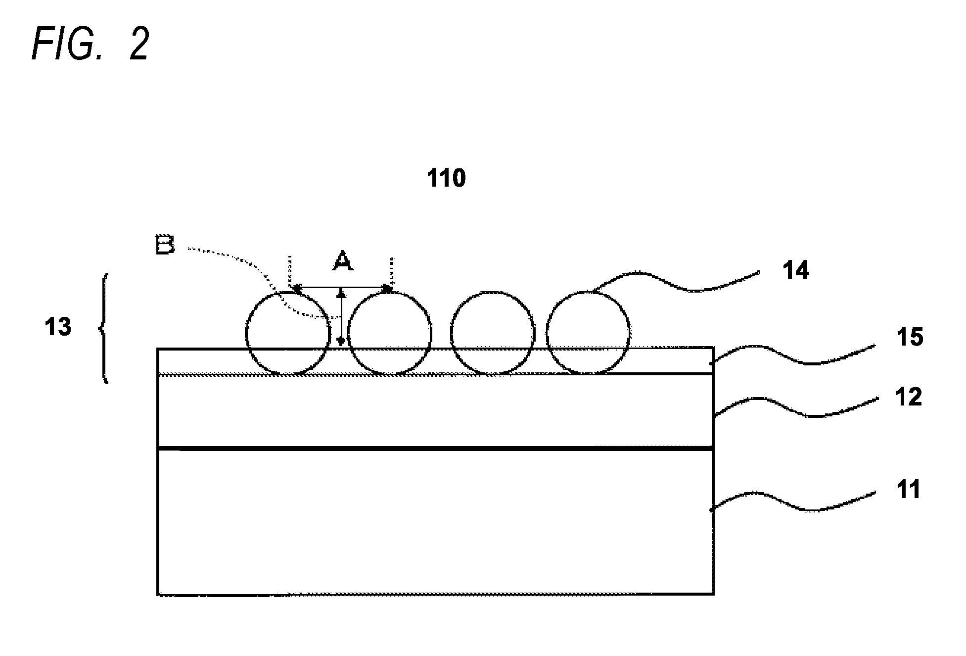
There is provided an antireflective film, including: a plastic substrate; a infiltration layer; and an antireflective layer containing metallic oxide fine particles with an average primary particle diameter of 50 nm to 250 nm and a viscosity increasing compound, in this order, wherein the infiltration layer contains a polymer of a (meth)acrylate compound having a molecular weight of 400 or less, and the antireflective layer has a moth-eye structure including an uneven shape formed by the metallic oxide fine particles.

Description

CROSS REFERENCE TO RELATED APPLICATION(S)[0001]This application claims priority from Japanese Patent Application Nos. 2014-186789 filed on Sep. 12, 2014, and 2014-200055 filed on Sep. 30, 2014, the entire disclosures of which are incorporated herein by reference.BACKGROUND[0002]1. Technical Field[0003]The present invention relates to an antireflective film, a polarizing plate, a cover glass, an image display device, and a method of manufacturing an antireflective film.[0004]2. Background Art[0005]In an image display device such as a cathode ray tube display (CRT), a plasma display (PDP), an electroluminescence display (ELD), a fluorescent display (VFD), a field emission display (FED), and a liquid crystal display (LCD), an antireflective film is provided in order to prevent contrast reduction or glare of the image due to the reflection of external lights on the surface of the display.[0006]As the antireflective film, an antireflective film has been known, which includes, on a substr...

Claims


Application Information

Patent Timeline
IPC IPC(8): G02B1/118G02B1/111G02B1/14G02B5/30
CPCG02B1/118G02B1/14G02B5/3033G02B1/111
Inventor ASAHI, MIHOKAMOHARA, KAZUOIBUKI, SHUNTAROMATSUMOTO, AYAKOWAKIZAKA, DAIKI
Owner FUJIFILM CORP
Learn More