
Silicon-contained material, negative electrode for use in non-aqueous electrolyte secondary battery, method of producing the same, non-aqueous electrolyte secondary battery, and method of producing the same

Inactive Publication Date: 2016-04-21
SHIN ETSU CHEM CO LTD
View PDF4 Cites 12 Cited by
  • Summary
  • Abstract
  • Description
  • Claims
  • Application Information

AI Technical Summary

Benefits of technology

The patent describes a silicon-contained material that can be used as a negative electrode in a non-aqueous electrolyte secondary battery. The material has good cycle performance, meaning it can be charged and discharged many times without losing its capacity. The inventive method of producing the negative electrode can provide a reliable and effective way to make batteries with long life for use in various applications.

Problems solved by technology

Although these conventional methods increase the charging and discharging capacities and energy density to some extent, the increase is insufficient for market needs and the cycle performance fails to fulfill the needs.
The conventional methods need to further improve the energy density and thus are not entirely satisfactory.
This method, however, cannot achieve low irreversible capacity at the first charge and discharge and a practical level of cycle performance; thus, there is room for improvement in this method.
Secondary batteries, however, are required to have a lifetime of 10 years or more when used for electric vehicles, and accordingly have an important problem of an improvement in their cycle performance.

Method used


Image

  • Silicon-contained material, negative electrode for use in non-aqueous electrolyte secondary battery, method of producing the same, non-aqueous electrolyte secondary battery, and method of producing the same
  • Silicon-contained material, negative electrode for use in non-aqueous electrolyte secondary battery, method of producing the same, non-aqueous electrolyte secondary battery, and method of producing the same
  • Silicon-contained material, negative electrode for use in non-aqueous electrolyte secondary battery, method of producing the same, non-aqueous electrolyte secondary battery, and method of producing the same

Examples


example 1

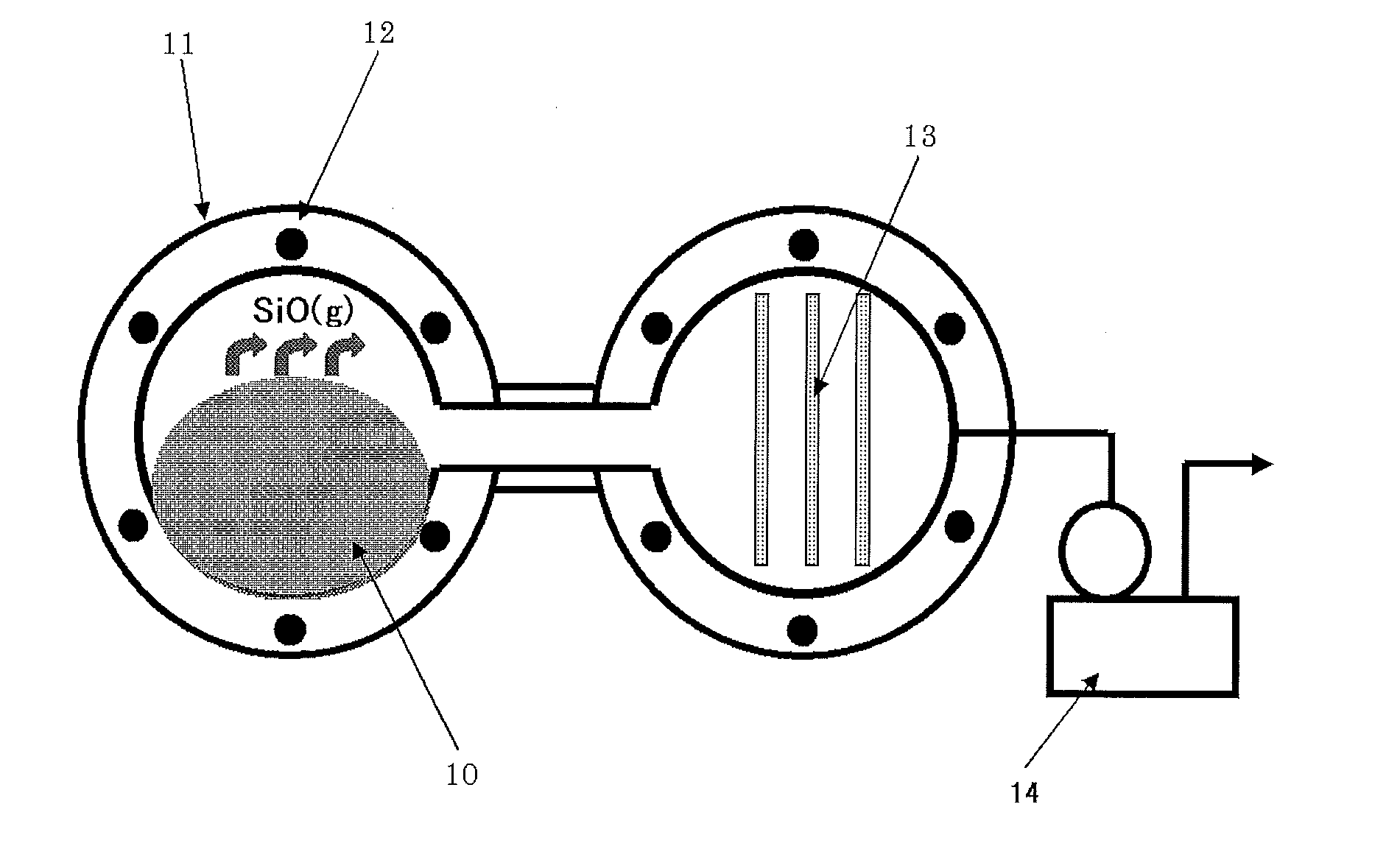
[0114]A reactor as shown in FIG. 7 was used. This reactor included a furnace 11, a heater 12, stainless steel bases 13 for precipitation, and a vacuum pump 14. Raw material powder 10 was introduced into the furnace 11. Specifically, fumed silica having an average particle size of 0.05 as silicon dioxide powder, and metallic silicon having an average particle size of 5 μm pulverized with a jet mill, as metallic silicon powder, were mixed in a metallic silicon powder-to-silicon dioxide powder mole ratio of 1.01. The obtained mixed powder was placed in the furnace 11 and heated at 1,420° C. under a reduced pressure of 40 Pa to generate silicon monoxide gas. The generated silicon monoxide gas was precipitated on the stainless steel bases 13, so that a silicon oxide lump was obtained. The obtained silicon oxide was pulverized with a ball mill, so that silicon oxide powder (SiOx where x=1.02) having an average particle size of 5 and a BET specific surface area of 4.8 m2 / g. After 200 g of ...

example 2

[0121]After 200 g of the same silicon oxide powder as example 1 was set on a silicon nitride tray, this powder was left in a furnace that can maintain the atmosphere; the powder was SiOx having an average particle size of 5 μm, and a BET specific surface area of 4.8 m2 / g where x=1.02. Then, argon gas was introduced into the furnace to replace the interior of the furnace with an argon atmosphere. The temperature in the furnace was increased at a heating rate of 300° C. per hour while a mixed gas of methane and argon was introduced at a rate of 2 NL / min. The temperature was maintained within the range from 600° C. to 1,000° C. for 3 to 10 hours, so as to perform thermal chemical vapor deposition (CVD) for a carbon coating. After the maintenance, the temperature was decreased until the temperature reached room temperature. The powder was then taken out. The amount of the deposited carbon of the obtained conductive silicon composite powder was in the range from 5.3% to 18.5%.

[Battery Ev...

example 3

[0123]The silicon-contained material in examples 1 and 2 was made of silicon oxide powder, subjected to the heat treatment and coated with carbon. Whether a high cycle performance effect of the invention can be achieved was checked even when another element was added. In production of a battery, conductive silicon composite powder that was doped with lithium in advance was produced. Lithium may be used to improve the first efficiency. Specifically, the conductive silicon composite powder (sample 10) having a B / A value of 0.65 obtained in example 2 and 5% of metallic lithium were added to an organic solvent and the resultant was mixed. The mixture was then dried. This obtained conductive silicon composite powder doped with lithium was heated at a heating rate of 300° C. / hour under an argon gas atmosphere and the temperature was maintained within the range from 500° C. to 800° C. for 3 to 8 hours.

[Battery Evaluation]

[0124]The battery with the obtained conductive silicon composite powd...


PUM


Abstract

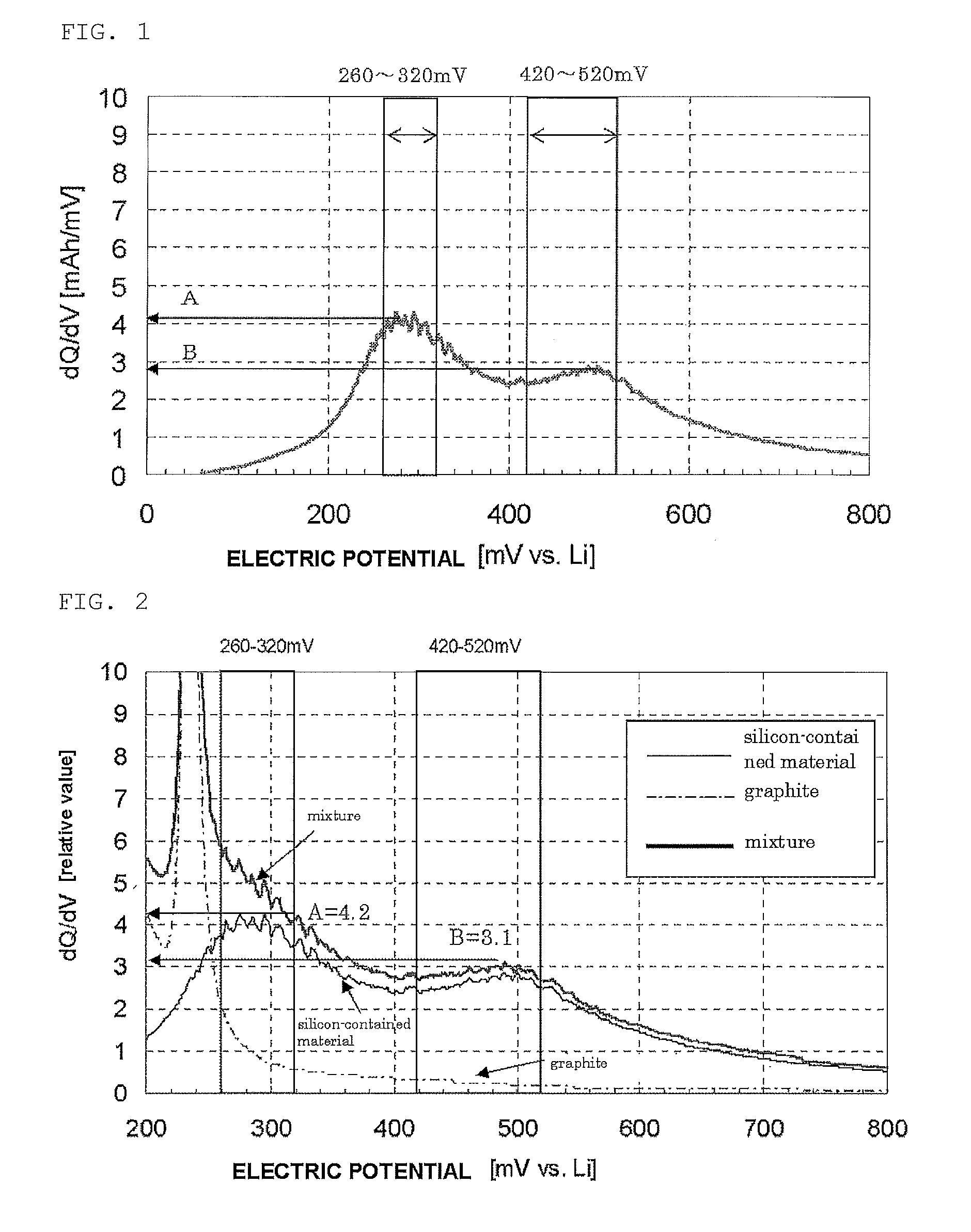
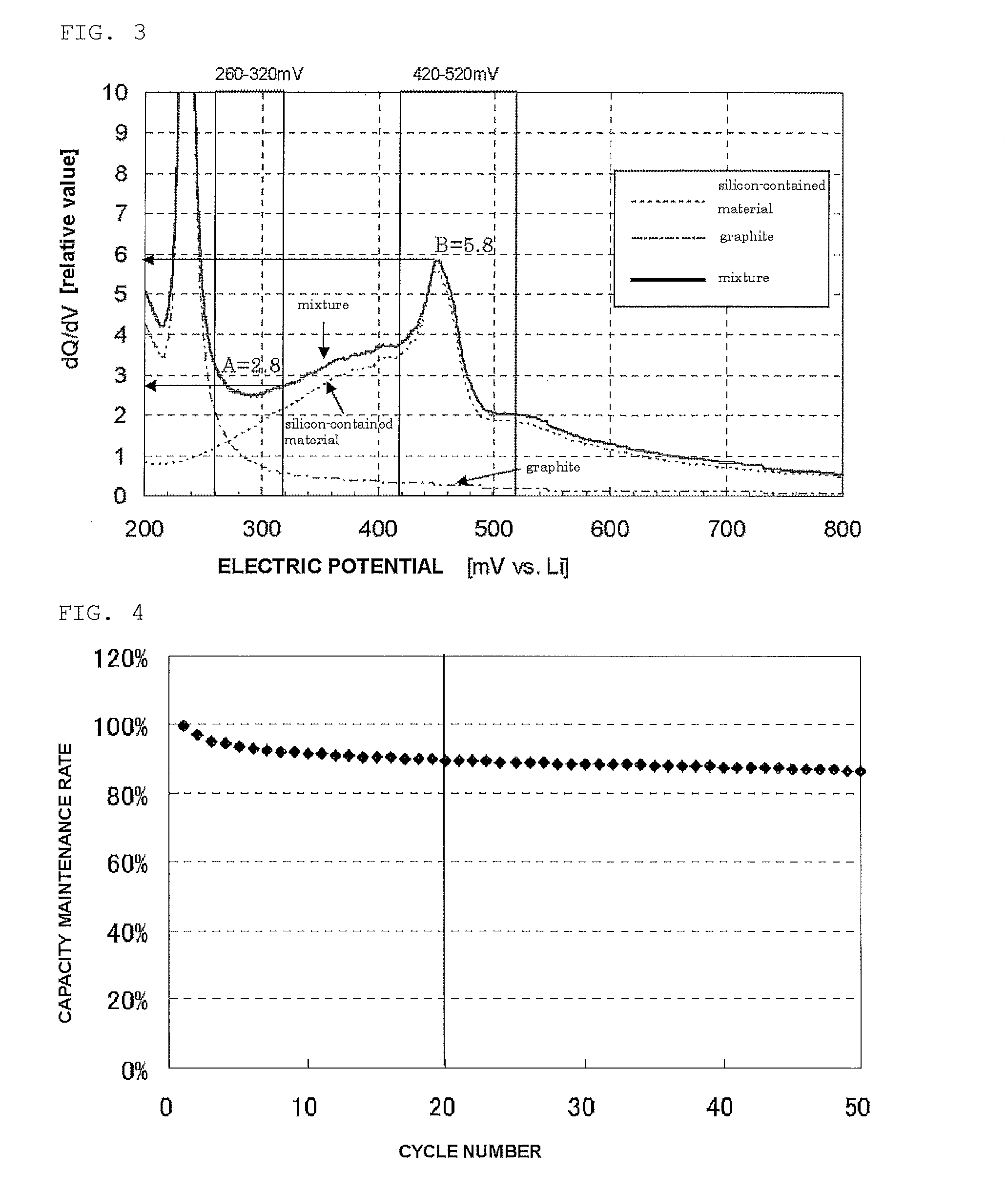
A silicon-contained material capable of being doped with lithium and de-doped, wherein when a three-electrode cell produced by using a working electrode including the silicon-contained material as an active material, a reference electrode made of metallic lithium, a counter electrode made of metallic lithium, and an electrolyte having lithium ionic conductivity is charged and discharged to graph a relationship between a derivative of a charging or discharging capacity with respect to an electric potential of the working electrode on the basis of the reference electrode and the electric potential, a ratio B / A is 2 or less while current flows in a direction in which the lithium of the silicon-contained material is de-doped in the discharge, A being the derivative maximum value with respect to a potential range from 260 to 320 mV, and B is the derivative maximum value with respect to a potential range from 420 to 520 mV.

Description

TECHNICAL FIELD[0001]The present invention relates to a silicon-contained material, a negative electrode for use in a non-aqueous electrolyte secondary battery, a method of producing the negative electrode, a non-aqueous electrolyte secondary battery, and a method of producing the battery.BACKGROUND ART[0002]As mobile devices such as mobile electronic devices and mobile communication devices have highly developed, secondary batteries with higher energy density are recently needed to improve efficiency and reduce the size and weight of the devices. The capacity of the secondary batteries of this type can be improved by known methods: use of a negative electrode material made of an oxide of V, Si, B, Zr or Sn, or a complex oxide thereof (See Patent Literatures 1 and 2, for example); use of a negative electrode material made of a metallic oxide subjected to melting and rapid cooling (See Patent Literature 3, for example); use of a negative electrode material made of a silicon oxide (Se...

Claims


Application Information

Patent Timeline
IPC IPC(8): H01M4/131H01M4/04H01M4/48H01M4/62H01M10/0525H01M4/1391
CPCH01M4/131H01M10/0525H01M4/1391H01M4/48H01M2220/30H01M4/0471H01M4/0402H01M4/0497H01M2004/027H01M4/625C01B33/113H01M4/366H01M4/483Y02E60/10Y02P70/50Y02T10/70
Inventor YOSHIKAWA, HIROKIKAMO, HIROMICHI
Owner SHIN ETSU CHEM CO LTD
Learn More