Protected Magnesium Alloys for Bioresorbable Stents

a bioresorbable stent and magnesium alloy technology, applied in the field of implantable devices, can solve the problems of bare mg alloy degradation too quickly, difficult to develop effective mg alloy modification or protection regimen, etc., and achieve the effect of uniform corrosion

Active Publication Date: 2016-05-12
MEDTRONIC VASCULAR INC
View PDF0 Cites 26 Cited by
  • Summary
  • Abstract
  • Description
  • Claims
  • Application Information

AI Technical Summary

Benefits of technology

[0007]Described herein are a variety of modification or protection regimens for inhibiting corrosion or slowing biodegradation of Mg alloys. The modification or protection regimens include one or more of removing secondary phases, such as precipitants or defects, from a surface of the Mg alloy to provide more uniform corrosion across the surface rather than focused localized corrosion, and providing a temporary barrier to water to the surface of the Mg alloy. Removal of secondary phases can be accomplished in any suitable manner, such as conversion coating the Mg alloy surface. One particularly effective conversion

Problems solved by technology

However, bare Mg alloys tend to degrade too quickly when implanted in a patient for the stents to effectively operat

Method used


Image

  • Protected Magnesium Alloys for Bioresorbable Stents
  • Protected Magnesium Alloys for Bioresorbable Stents
  • Protected Magnesium Alloys for Bioresorbable Stents

Examples


example 1

Combination of HF Conversion Coating and Nanolaminate

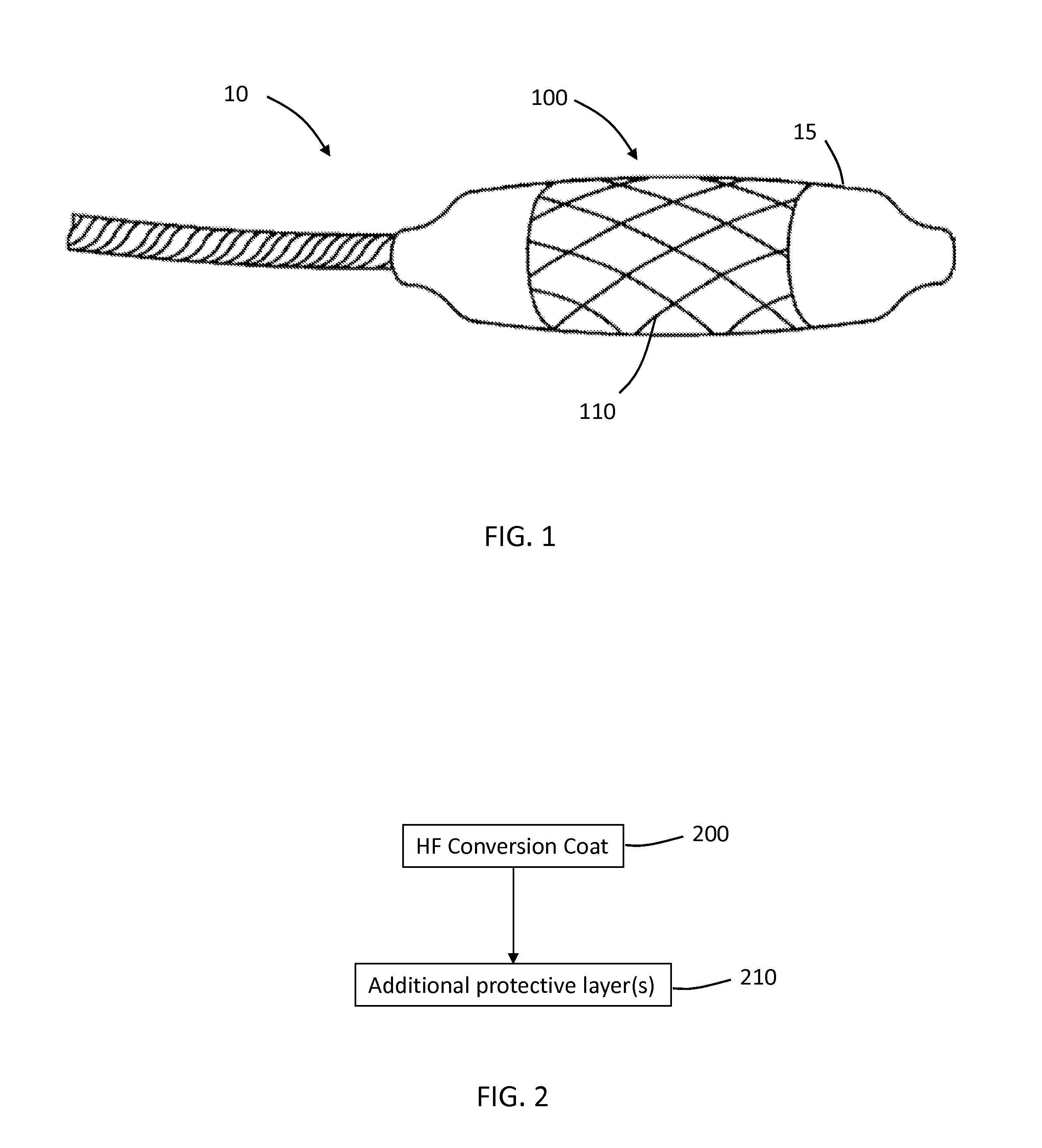
[0134]AE42 Mg alloy stents were immersed in a 49% HF solution for a 24 hour immersion time at ambient conditions to conversion coat the Mg alloy with hydrous MgF2 having a thickness of about one to two microns. The resultant film was uniform and dark in appearance. Compare FIG. 11A, which is an image of a bare electropolished Mg alloy stent, to FIG. 11B, which is an image of an electropolished Mg alloy stent post HF treatment. The treatment resulted in the removal of precipitants and defects on the surface of the stent, which was shown to cause more uniform corrosion.

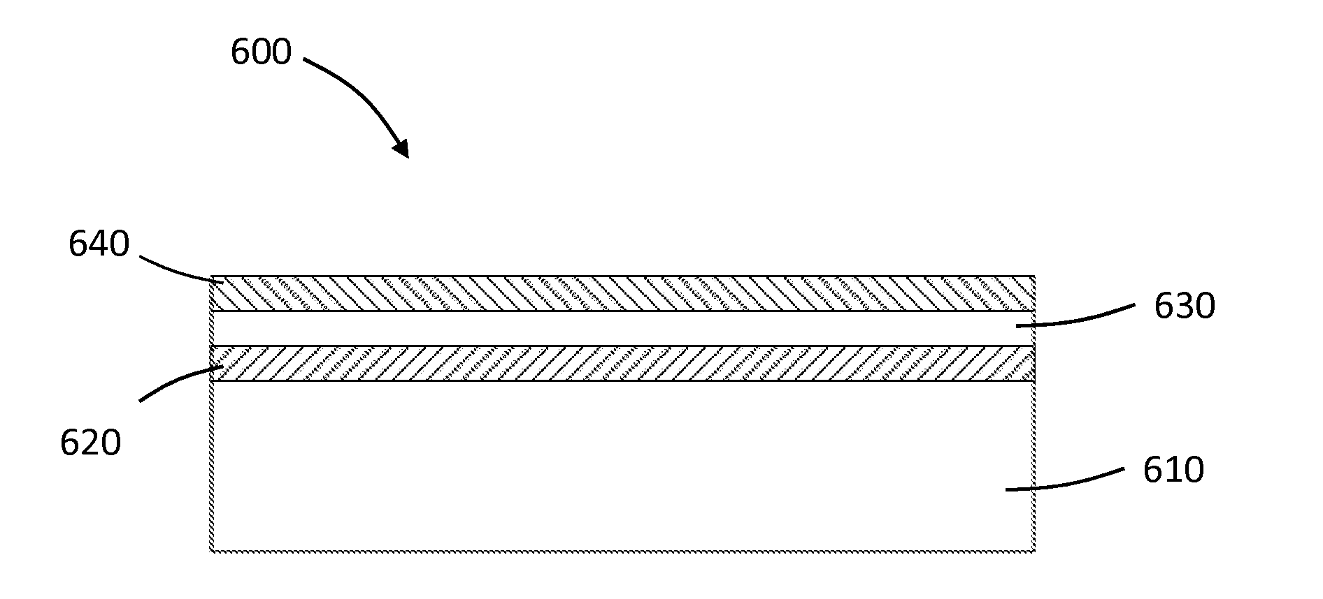
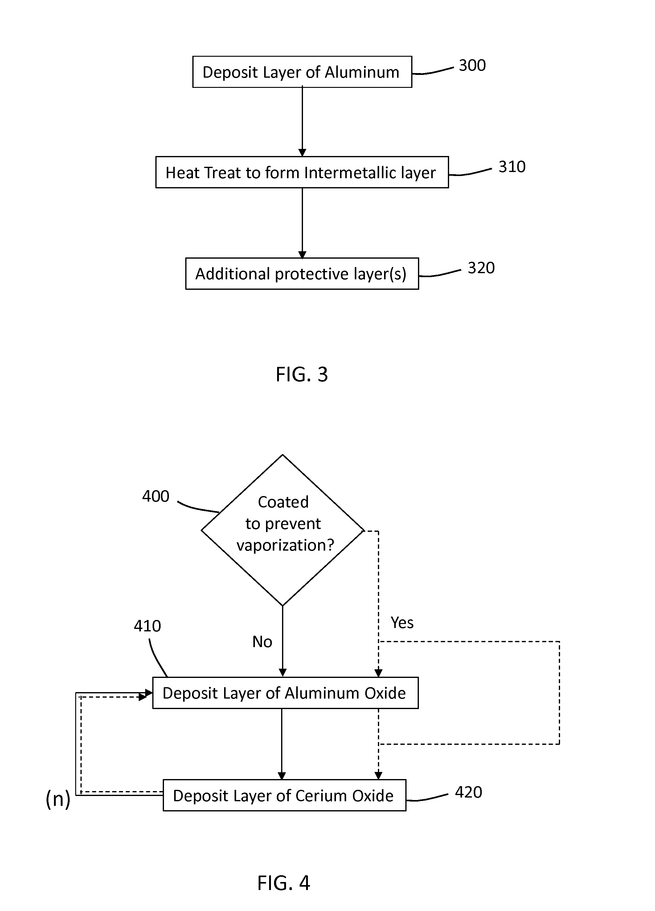
[0135]An aluminum oxide coating or a coating of a nanolaminate of aluminum oxide and alucone was applied to HF conversion coated AE42 Mg alloy stents, thermal oxide treated AE42 Mg alloy stents, and bare AE42 Mg alloy stents.

[0136]Thermal oxidation of AE42 Mg alloy stents was carried out as follows. Briefly, the Mg alloy stents were heated at 485° C. for 6 hours in an...

example 2

Aluminum Oxide and Cerium Oxide Coated Magnesium Alloy Stents

[0148]Bare Mg alloy (AE42) and aluminum oxide coated Mg alloy (AE42 with 100 nm of aluminum oxide deposited by ALD at 95° C.) samples were subjected to in vitro corrosion testing, generally as described above regarding Example 1. The percent metal remaining in such stents after 2 weeks and 4 weeks of corrosion testing are shown in FIG. 18. As shown, atomic layer deposition (ALD) of aluminum oxide (Al2O3) on magnesium alloy can be an effective way to slow corrosion (FIG. 18). However, when placed on a stent that is crimped and deployed and subjected to fatigue in vivo, aluminum oxide coatings may not sufficiently slow corrosion of the Mg alloy to allow effective stent function for a desired amount of time. See, for example, FIG. 12 and associated discussion above in Example 1.

[0149]Cerium has also been shown in a variety of literature to act as a corrosion inhibitor for magnesium alloys. However, cerium nitrate conversion c...


PUM

PropertyMeasurementUnit
Temperatureaaaaaaaaaa

Abstract

Biodegradable magnesium alloy implantable medical devices are protected to delay onset of corrosion, and thus biodegradability, or to corrode more uniformly. The protection allows for extended effective use of the devices while maintaining biodegradability. Examples of protective coatings include conversion coatings that at least partially remove exposed second phases from a surface of the magnesium alloy and coatings that provide a barrier between water and the surface of the magnesium alloy.

Description

FIELD[0001]This disclosure generally relates to, among other things, implantable medical devices; and more particularly to implantable devices, such as stents, that include biodegradable magnesium alloys.INTRODUCTION[0002]Stents in general are prostheses or implants that can be inserted into a vessel or passageway of a patient and when deployed presses against the vessel or passageway. Stents are often endovascular prostheses or implants that are used for treating, for example, stenosis or aneurysms. Stents may include a support structure or frame that is capable of supporting a wall of a vessel or bypass an aneurysm. In many cases, the structural features of the stent consist of the frame.[0003]Stents are typically inserted into a vessel in a compressed or crimped state and then expanded when properly positioned such that the frame presses against the wall of the vessel. The stents can be expanded with the aid of, for example, a balloon catheter or may be self-expandable.[0004]Sten...

Claims


Application Information

Patent Timeline
IPC IPC(8): A61L31/08A61F2/915A61L31/10A61L31/02A61L31/14C23C16/06A61F2/89
CPCA61L31/088C23C16/06A61F2/915A61F2/89A61L31/022A61L31/148A61L2420/08A61L31/084A61F2002/91541A61F2002/91575A61F2210/0076A61F2230/0069A61L2420/02A61L31/10
Inventor PULUGURTHA, SYAMALA RANIALLEN, JEFFREYMITCHELL, JAMESSTORMENT, CHRISTOPHERMENDELSON, JILL
Owner MEDTRONIC VASCULAR INC
Why Eureka
Try Eureka