Fluidized-bed boiler integrating multifunctional inertia-gravity separator with multiple furnace profiles

a technology of inertia-gravity separator and fluidized bed, which is applied in the direction of fluidized bed combustion apparatus, lighting and heating apparatus, combustion types, etc., to achieve the effect of reducing the emission of other pollutants, improving the efficiency of desulfurization and denitrition, and fume velocity at the inlet end

Inactive Publication Date: 2016-05-26
WANG LING +1
View PDF7 Cites 9 Cited by
  • Summary
  • Abstract
  • Description
  • Claims
  • Application Information

AI Technical Summary

Benefits of technology

[0050]According to the method for improving the efficiency of desulfurization and denitrition and reducing emission of other pollutants provided by the present invention, there are three sections within the hearth for three-stage air supply, i.e., a boiling combustion section from an air distribution plate to the upper end of a transition section, a suspending combustion section from the upper end of the transition section to the middle upper part of the hearth, and a high-temperature combustion section at the upper part of the hearth. The two sections in the middle lower part, with a temperature kept at about 50° C.; and the third section in the middle upper part provides for three-stage air supply, and the temperature inside a large capacity-capacity-expanding space from the third section to the separator is kept at about 950° C.
[0051]Primary multifunctional inertia-gravity high-temperature separator: a downward flue and an upward flue, a turning passage, a large capacity-capacity-expanding space (burn-out chamber) and a lower storage bin, which are made of membrane water-cooling walls or water-cooling walls and refractory material in a sealed manner, are disposed in a space from the rear wall of the hearth to the front wall of the shaft. Different fume velocities are respectively defined with respect to the different flowing segments of the downward flue, the upward flue, the turning passage and the large capacity-capacity-expanding space (burn-out chamber). Specifically, the fume velocity at the outlet end of the downward flue is increased, the fume velocity at the inlet end of the downward flue is decreased, the magnification of sudden expansion and velocity reduction into the large capacity-capacity-expanding space is increased, the compact inertia of gas and solid from high to s increased to enhance the efficient gas-solid separation, the continuous combustion of combustible material in the burn-out chamber (large capacity-capacity-expanding space) is reinforced, the fume velocity at the inlet segment of the upward flue is decreased to reduce the amount of ash in the airflow, the wear to the convectional heater face is completely eliminated, and the fume velocity of the segments above the inlet segment of the upward flue is increased to enhance the efficient heat transfer of the high-temperature airflow and high-temperature ash with the over-heater.
[0052]By the primary high-temperature separation under the effect of the water-cooling wall of the guiding gas-solid directly-raising storage bin, the fume is forced to descend sharply by 180° from the outlet of the hearth so that gas and solid flow in the same direction and directly raise to the large capacity-capacity-expanding space to the storage bin through the downward flue, so that highly concentrated solid particles are subject to a sharp centrifugal force and drag force first; the falling velocity of solid is made higher than that of airflow due to the vertical downward-flowing of both gas and solid in the same direction, the blowing of airflow, the weight of solid, the gravity and the vertical falling force from high to low; when the fume turns at a low velocity, fine particles having a specific gravity higher than that of air directly and quickly fall to the bottom of the storage bin; ash continuously burns in the large capacity-capacity-expanding space and burns out, smoke is subject to twice downward and upward turn-over inertia separation by 180° in the separator and a collision-type inertia separation with the over-heater within the upward flue and finally directly falls to the large capacity-capacity-expanding space for continuous combustion until burning out; and part, of the bum-out ash is settled in the storage bin, while the other part is carried away by airflow for convective heat-exchange with the over-heater and the coal economizer and then enters the secondary separator for separation.
[0053]A secondary inertia-gravity low-temperature separator is provided; the secondary low-temperature separator is disposed at the intersection of the lower ends of the plurality of over-heaters or coal economizers within the shaft of the membrane wall, the rear wall of the primary separator and the oblique transition segment of the rear wall of the large capacity-capacity-expanding space, a part in the middle or slightly anterior of a space from the front wall to the rear wall of the secondary low-temperature separator is divided into a downward flue and an upward flue for the secondary low-temperature separator; under the effect of the guiding fume directly-raising storage bin spacer, the fume is forced to change by a large angle and to flow in the same direction to directly raise to the capacity-expanding space to the storage bin through the downward flue; ash having a specific gravity higher than that of air falls to the bottom of the storage bin through the large capacity-capacity-expanding space due to the blowing of airflow, the weight of ash and the gravity; once the ash falls to the bottom of the storage bin, due to the distance from the bottom of the storage bin to the upward flue of the secondary separator, the ash carried away is limited even the fume velocity reaches the maximum economic velocity; the secondary separation is subject to one large oblique-degree change, one downward and upward turn-over separation by 180° and sudden expansion and velocity reduction for settlement due to gravity, so that the initial emission concentration of smoke from the boiler can be lower than the national environmental-protection standards for layer-burning chain boils.
[0054]In order to solve the technical problems of the known technologies, the present invention employs the following technical solutions. A fluidized-bed boiler integrating a multifunctional inertia-gravity separator and a plurality of models of boilers is provided, having a primary high-temperature inertia-gravity separator: the rear wall of the membrane wall of the hearth and the front wall of the membrane wall of the shaft form the front wall and rear wall of this separator, a space from the rear wall of the hearth to the front wall of the shaft is divided by the membrane wall of the guiding gas-solid directly-raising storage bin into an upward flue and a downward flue, the large capacity-capacity-expanding space (burn-out chamber) and its turning passage and the storage bin are at the lower ends at the outlet of the downward flue and the inlet of the upward flue, a high-temperature over-heater is mounted in the vertical segment of the upward flue so that this separator naturally has multifunctional properties of efficient gas-solid separation, efficient heat transfer and complete combustion. The downward flue and the upward flue are resisted against and communicated to the lower part of the rear wall of the hearth in a sealed manner through the turning passage and through the storage bin, the dipleg and the back-feeding valve all sealed below the flues. The front upper part of this separator is the fume inlet while the rear upper part thereof is the fume outlet. The four walls of this separator are heated water-cooling walls integrally communicated to the hearth and the shaft. The front membrane wall and rear membrane wall of this separator and the membrane wall of the guiding gas-solid directly-raising storage bin are in low circulation ratio, and are all exposed two-sided heating faces except for partial wear measures on the wall face of the downward flue. Thus, both the heated area and the heat exchange effect are increased, and 100% thermal insulating material may be saved for three wall faces. The upper ends of the membrane walls on two sides of this separator are communicated to the upper vertical header while lower ends thereof are communicated to the lower vertical header, and the two sides of the separator are sealed by thermal insulating material. A secondary low-temperature inertia-gravity separator is disposed at the lower ends of the plurality of over-heaters or coal economizers within the shaft of the membrane wall. The front wall of the secondary high-temperature inertia-gravity separator is completely the rear wall of the primary separator and the oblique transition segment of the rear wall of the large capacity-capacity-expanding space, while the rear wall thereof is the rear wall of the shaft and the guiding fume up-down turn-over spacer. The part in the middle or slightly anterior of a space from the front wall to the rear wall of the secondary low-temperature separator is divided into a downward flue and an upward flue for the secondary low-temperature separator. The capacity-expanding space and the storage bin are disposed in a space from the rear outer wall of the primary storage bin to the front outer wall of the shaft. The guiding fume directly-raising storage bin spacer is highly obliquely disposed in the middle or slightly anterior of the front and rear walls, with its upper lower being sealed against the rear wall of the shaft, its lower end being far away from the capacity-expanding space by a certain distance, and its two side ends being sealed against the bilaterally symmetric membrane wall. The guiding fume up-down turn-over spacer is highly obliquely disposed to be parallel to the downward flue and the upward flue, with its lower end being sealed against the front wall of the expanding wall or far away from the front wall of the expanding wall by a certain distance to be sealed against the front wall of the shaft, its upper end being extended to the center or slightly anterior of the shaft, and its two sidewalls and rear wall thereof being sealed by thermal insulating material.

Problems solved by technology

However, such high-temperature cyclone separators mainly have the disadvantages of high resource consumption, many performance shortcomings, high wind velocity and large resistance at the tangential inlet, and high power consumption of the draft fan; and have the following serious shortcomings: due to the high-velocity reverse flowing of gas and solid from the output of the hearth to the storage bin, a large amount of ash is carried in the airflow; the initial emission concentration of fume is very high, so the wear-resistant process to the fume inlet on the convection heating face is made completed and the convection heating face is likely to be worn and to have dust deposited thereon; the service life of the boiler is shortened, the thermal resistance is increased, the heat transfer coefficient is decreased, and the deashing strength is weakened.
Although these two separation modes can improve the wear, they have the following largest disadvantage that fine particles and ash carried by airflow from the outlet of the hearth can not continue to combust so that the content of carbon in ash is high.
Although this separation mode has the advantage of reducing the content of carbon in ash, the high original emission concentration of fume is still not solved, and the use of wear-resistant measures at the inlet end of the convection heating face is complicated and still has hazards.
As a dry cyclone separator utilizes a large amount of wear-resistant and thermal insulating material, both the raw material cost and the manufacturing and installation cost of the separator are increased, large thermal inertia and thermal loss are also caused, Such a separator is likely to suffer coke formation at a high temperature, and the boiler is slow to start and stop.
Such a gas-solid separation mode not only artificially increases the flowing resistance and the power consumption, but also reduces the separation efficiency and makes a large amount of ash in the airflow, and the separation elements are likely to be deformed and damaged.
Therefore, circulating fluidized-bed boilers using various inertia separators ever popular in China have been gradually driven out of the market.
As the circular steam-cooling cyclone separators have high steel consumption, complicated manufacturing process and thus high price, it is difficult for customers to use such circular steam-cooling cyclone separators, thereby resulting in very low market share.
Although square steam-cooling cyclone separators have low steel consumption and superior manufacturing process, the separation efficiency and stability of the square steam-cooling cyclone separators are lower than those of the circular steam-cooling cyclone separators.
As the rear wall of the hearth and the front wall of the shaft absolutely may be used as the common wall of the front and rear ways of the separator, the tube bundle in the vertical segment of the front and rear was of the separator is unnecessary and has negative effects.
If the fume velocity of the upward flue of the separator is ≦3 M, the volume will certainly be increased greatly, so that it is inappropriate for development towards large scale.
A secondary low-temperature downward-exhaust cyclone separator has the following shortcomings that: first, the flowing resistance is high; second, the separation efficiency is low; and third, it is unable to realize automatic discharge of deposited ash from the rear of the ventilator.
1. Ultra-low resistance saves the power consumption of the draft fan. This is because the fume flow velocity of the separator is lower than the flow velocity of the cyclone separator.
2. Ultra-low energy consumption saves raw material. This may be indicated by saving by 90% of the wear-resistant material, by 50-80% of thermal insulating material, and by 100% of the metal material of a non-heating surface heat-resistant steel ventilator, a heat-resistant steel mesh and a steel cylinder of a dry high-temperature cyclone separator: and saving by 30-60% of steel and wear-resistant material and by 50-70% of thermal insulating material of a steam-cooling circular cyclone separator.
3. Ultra-low dust emission saves the investment in dust removing equipment and cost in maintenance and replacement. This is because, the highest value of the original emission concentration of the boiler fume by two-stage separation may be 3.
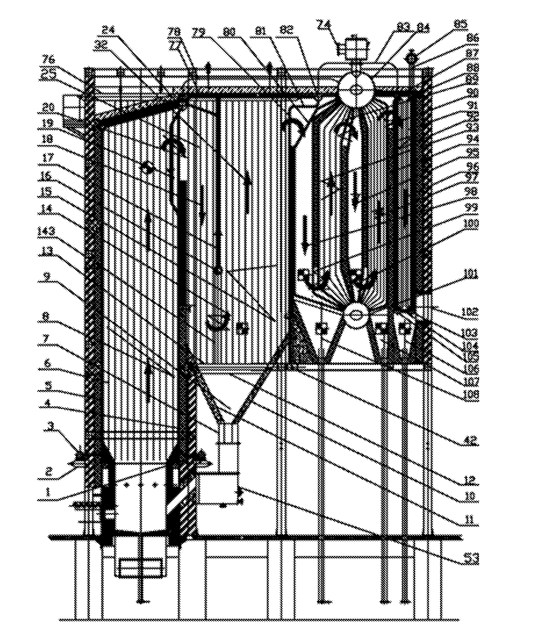
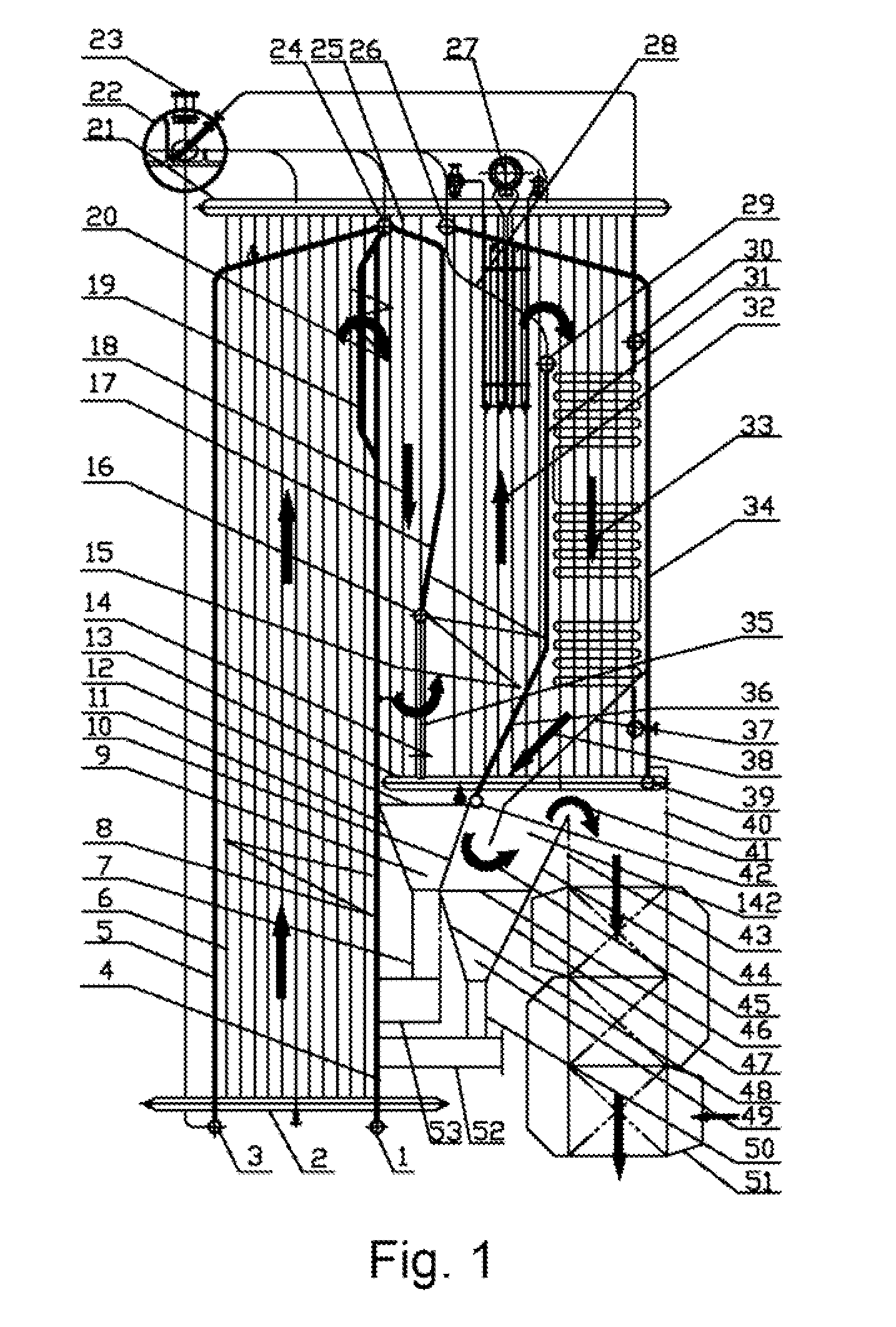
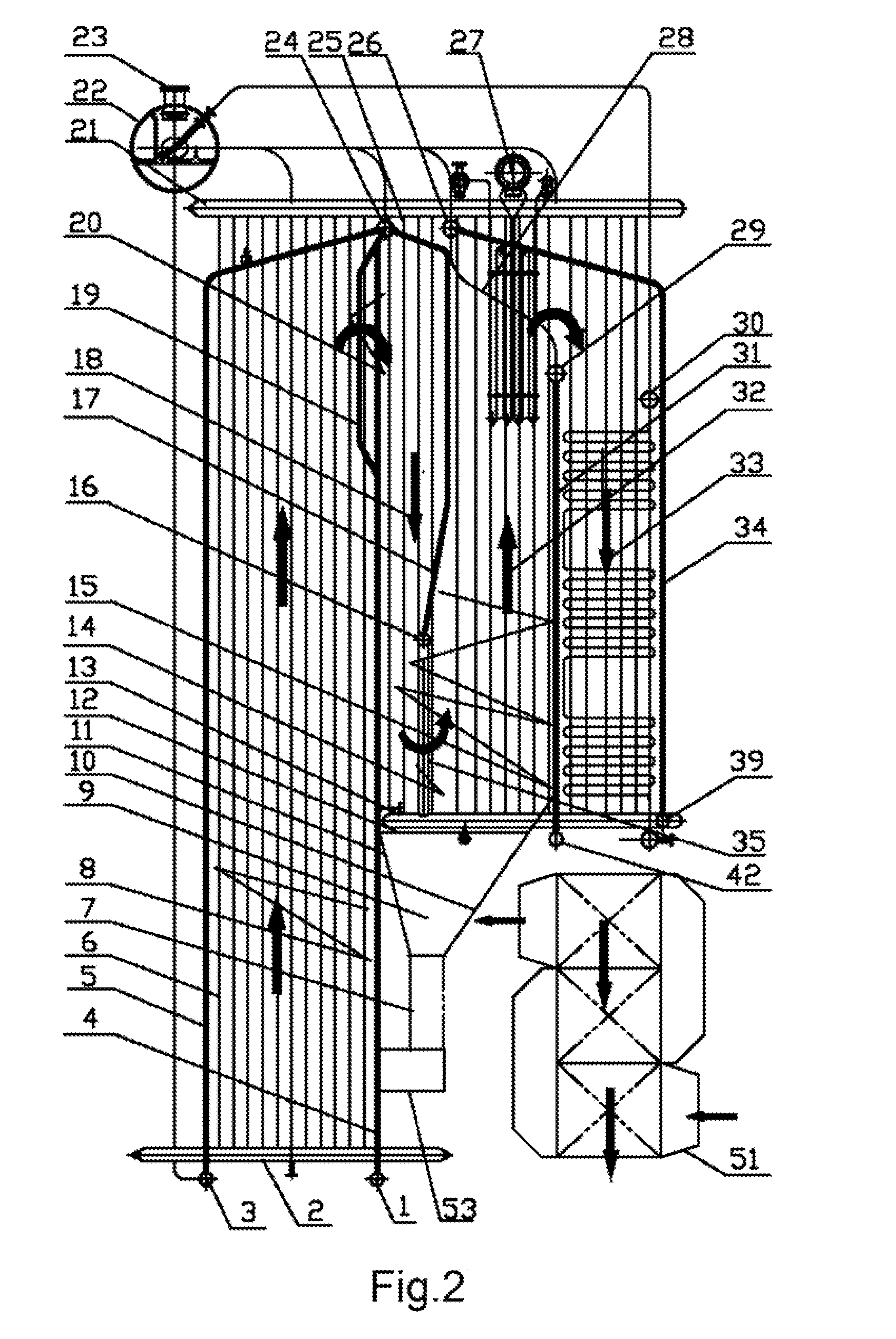
4. Ultra-high separation efficiency eliminates the wear to the convection heating face and prolongs the service life of the whole boiler. This is because, the solid is directly conveyed to the storage bin by airflow under the action of a guiding fume directly-raising storage bin water-cooling wall, high concentration of gas and solid from the outlet of the hearth comes down with a sharp turn of 180° and then flows in a same direction to directly to the large capacity-expansion space to the storage bin; and, the sharply turned centrifugal force and drag force, blowing force of the airflow, the gravity of the solid and the ground gravitation may allow the velocity of the solid falling from up to down to be higher that the velocity of the airflow, so that the large capacity expansion of the high velocity outlet of the downward flue and the low velocity inlet of the upward flue create a condition that the separable specific gravity is higher the fine particles and ash in air.
5. Ultra-high combustion efficiency reduces the carbon content of the combustible. This may be indicated by the efficiency of the separator and multi-stage separation, particularly the downward and upward flues, the turning passage and the large capacity-capacity-expanding space increasing the burn-out time of the combustible at the height of nearly the hearth in the boiler.
6. The advantage that the ultra-high separation efficiency of the first-stage water-cooling high-temperature separation may allow the shaft flue and convection heating face of a low-pressure steam and large-scale heating boiler to employ a shell shaft thread flue convection heating face and allow for shaft flue sealing and convective heat transfer strength is irreplaceable.
7. Two shortcomings of high-temperature coking due to low an ash fusion point and high-temperature corrosion of the heater during biomass and urban garbage power generation may be solved. This may be indicated by the radiative heat transfer and burn-out of the downward and upward flues and the large capacity expansion space of the full-water-cooling separator and the arrangement of the over-heater not in the separator.
8. The reduction of the carbon content of ash improves comprehensive energy efficiency. This may be indicated by the ultra-high consumption efficiency and the Ultra-low original fume emission.
9. Saving the maintenance cost of the separator improves comprehensive energy efficiency. This may be indicated by the water-cooling separator.
If any carelessness, it is difficult to avoid the wear of the heating surface.

Method used


Image

  • Fluidized-bed boiler integrating multifunctional inertia-gravity separator with multiple furnace profiles
  • Fluidized-bed boiler integrating multifunctional inertia-gravity separator with multiple furnace profiles
  • Fluidized-bed boiler integrating multifunctional inertia-gravity separator with multiple furnace profiles

Examples


embodiment 1

[0299]Referring to FIG. 1, a fluidized-bed boiler integrating a multifunctional inertia-gravity separator and a plurality of models of boilers is a circulating fluidized-bed boiler having a full-membrane-wall or full-water-cooling hearth, a full-water-cooling separator, a full-water-cooling shaft and a full-water-cooling ceiling.

[0300]A primary high-temperature water-cooling inertia-gravity separator is disposed in a space from the rear wall 4 of the hearth to the front wall 31 of the shaft. The front wall of the separator is completely the rear wall 4 of the hearth, and the rear wall 31 of the separator and the oblique transition segment 36 of the rear wall of the large capacity-capacity-expanding space share a wall with the front wall of the shaft. A guiding gas-solid directly-raising storage bin water-cooling wall 17 is disposed in the middle or slightly anterior or more anterior of a space between the front wall and the rear wall of the separator and is divided into a downward f...

embodiment 2

[0311]Referring to FIG. 2, the difference between this embodiment and Embodiment 1 is mainly the single-stage water-cooling inertia-gravity separator, the lower end of the vertical segment of the tube bundle on the rear wall 31 of which is communicated to the lower horizontal header 42 on the rear wall of the separator.)

embodiment 3

[0312]Referring to FIG. 3, the difference between this embodiment and Embodiment 2 is mainly that the convectional heater face of the shell shaft 58 is a threaded flue tube 59; the upper tube plate 57 of the shell is communicated to the lower end of the communicating tube 56 while the upper end thereof is communicated to the horizontal header 55; the upper end of the horizontal header 55 is communicated to the lower end of the communicating tube 54; the upper end of the communicating tube 54 is bent forward and upward and obliquely extended to be communicated to the horizontal header 26 and to form the water-cooling ceilings of both the upward flue 32 of the separator and the shell shaft; the rear end of the horizontal header 55 is vertical to, parallel to or exceeds the rear end of the shell shaft 58 by a certain distance to meet the requirement of constructing the rear wall of the shaft; and the distance from the lower end of the horizontal header 55 to the upper tube plate 57 of ...


PUM


Abstract

A fluidized-bed boiler integrating a multifunctional inertia-gravity separator and a plurality of models of boilers, the fluidized-bed boiler being a steam boiler, a hot-water boiler or a phase-transformation boiler, the fluidized-bed boiler comprising a hearth, a single/double horizontal drum, a vertical single-drum/double-drum, vertical and horizontal headers, vertical and horizontal membrane wells, a primary high-temperature inertia-gravity water-cooling separator, a secondary low-temperature inertia-gravity water-cooling separator(a double-stage inertia-gravity water-cooling separator), a single-stage high-temperature water-cooling inertia-gravity separator, an equalizing, separating and heat storing device, a membrane water-cooling wall shaft, a shell shaft and a dry-wall shaft, the primary, secondary and single-stage inertia-gravity separators comprising a guiding gas-solid directly-raising storage bin water-cooling wall, a guiding fume directly-raising storage bin spacer, a downward flue, an upward flue, a turning passage, a large capacity-capacity-expanding space, a storage bin and a back-feeding device, characterized in that the primary high-temperature water-cooling inertia-gravity separator is disposed in a space between the rear wall of the hearth and the front wall of the shaft; the secondary low-temperature water-cooling inertia-gravity separator is disposed at the height-equal border of the lower end of a multi-stage over-heater or coal economizer within the shaft and a bending point of the lower end of a vertical segment of the rear wall of the primary high-temperature separator, and extends downward; a fume inlet is separately provided in the front upper part of each of the two-stage separators, and a fume outlet is separately provided in the rear upper part thereof; and the front sidewall and a rear sidewall are a heated water-cooling wail and an insulating wall, which are integrated to the main body of the boiler.

Description

CROSS-REFERENCE TO RELATED APPLICATIONS[0001]This application is a continuation-in-part of International Patent Application No. PCT / CN2014 / 092168 with an international filing date of Nov. 25, 2014, designating the United States, now pending. The contents of all of the aforementioned applications, including any intervening amendments thereto, are incorporated herein by reference.TECHNICAL FIELD[0002]The present invention relates to circulating fluidized-beds integrating a multifunctional inertia-gravity separator with a plurality of models of boiler main bodies, including hot-water boilers, steam boilers, phase-transformation hot-water boilers, heat and power cogeneration boilers and power plant boilers; particularly relates to an ultra-large circulating fluidized-bed power plant boiler and a large-scale phase-transformation hot-water boiler for centralized heating; and relates to the energy-saving and emission-reducing improvement of various circulating fluidized-bed boilers, pulver...

Claims


Application Information

Patent Timeline
Patent Type & Authority Applications(United States)
IPC IPC(8): F22B31/00F23C10/10
CPCF22B31/0015F22B31/0076F23C10/10F22B31/0061F22B31/0084F23C10/08F01K5/00
Inventor WANG, SEN
Owner WANG LING
Why Eureka
Try Eureka