
Preparation method of catalyst comprising a ruthenium-containing catalyst layer formed on the body surface

Active Publication Date: 2017-01-05
KOREA INST OF ENERGY RES
View PDF8 Cites 2 Cited by
  • Summary
  • Abstract
  • Description
  • Claims
  • Application Information

AI Technical Summary

Benefits of technology

The present invention provides a method for preparing a ruthenium-containing catalyst that exhibits excellent catalytic performance in various reactions for producing hydrogen using a ruthenium catalyst. The catalyst has a large specific surface area, resulting in increased efficiency and a reduction in the amount of expensive precious metal catalyst used, resulting in a cost saving effect for the production system of hydrogen and synthetic gas. The method involves first aging the mixed solution of a precipitating agent and a ruthenium precursor-containing solution to form ruthenium-containing precipitate seeds, which are then secondarily aging to grow the seeds and contacting them and the substrate to deposit the particles on the surface of the substrate, resulting in a highly dispersed and uniform thickness ruthenium-containing catalyst layer. This catalyst layer has a structure wherein round shaped ruthenium-containing precipitate particles are piled to form a large specific surface area, making it ideal for various reactions for producing hydrogen. Compared to conventional pellet catalyst, the catalyst coated with a small amount of ruthenium makes reduced reactor size possible and reduces the amount of expensive precious metal catalyst used, resulting in a cost savings effect for the production system of hydrogen and synthetic gas.

Problems solved by technology

In achieving a certain amount of catalyst loading, the impregnation method has the problems of increase of number of impregnation and difficult control of dispersion of the active metal particles due to the low catalyst loading amount.
Also, the washing coating has the problem of the weak binding strength between the catalyst coating layer and the metal substrate since controlling coating layer thickness and uniform coating are difficult.
Furthermore, it needs a large amount of catalyst due to the much loss of coating solution.
However, when a precursor of a ruthenium catalyst was applied to the above method to form a ruthenium catalyst layer, the coating layer of the ruthenium catalyst was not formed well on the metal substrate surface.
Thus, according to the above method, it was not easy to form a ruthenium catalyst layer exhibiting appropriate catalytic activity.

Method used


Image

  • Preparation method of catalyst comprising a ruthenium-containing catalyst layer formed on the body surface
  • Preparation method of catalyst comprising a ruthenium-containing catalyst layer formed on the body surface
  • Preparation method of catalyst comprising a ruthenium-containing catalyst layer formed on the body surface

Examples


example 1

Analysis of Ruthenium Coating Layer Depending on pH of Precipitation Reaction Solution of Ruthenium Precursor

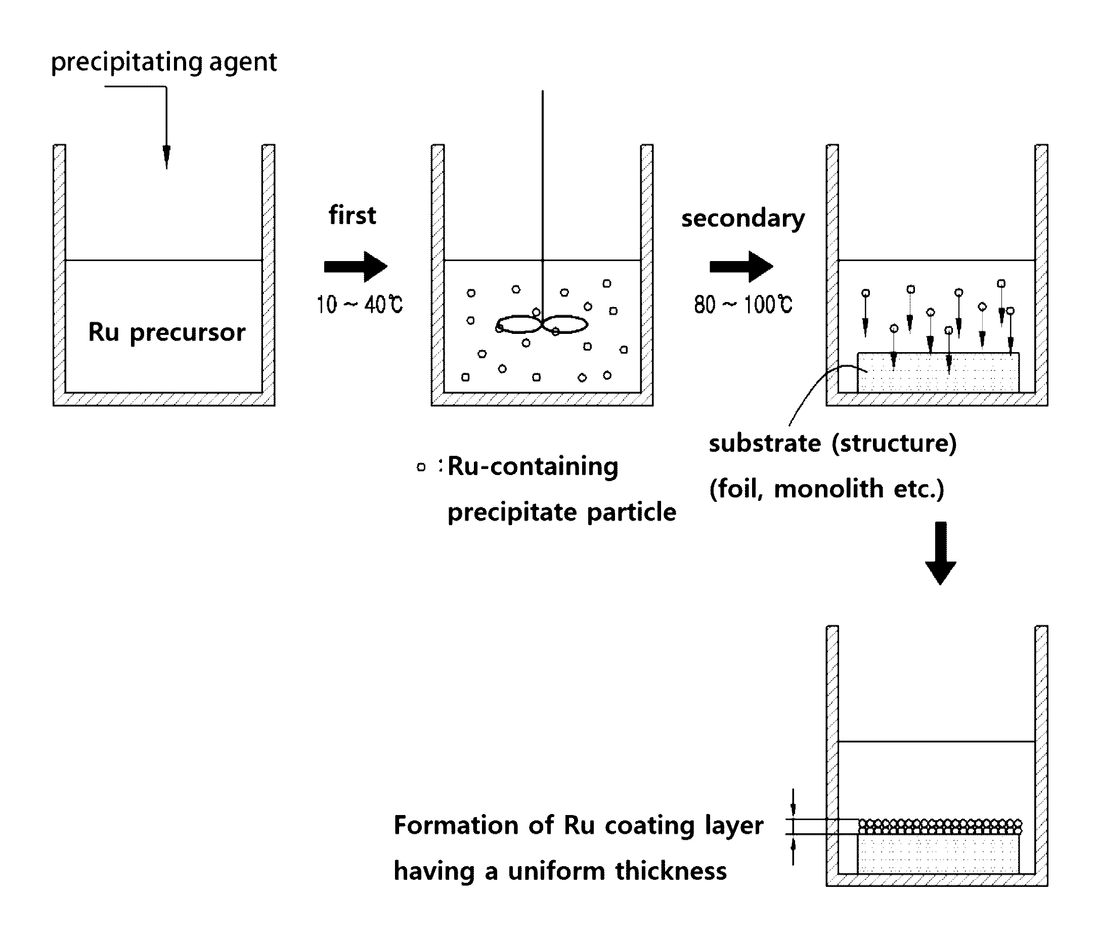
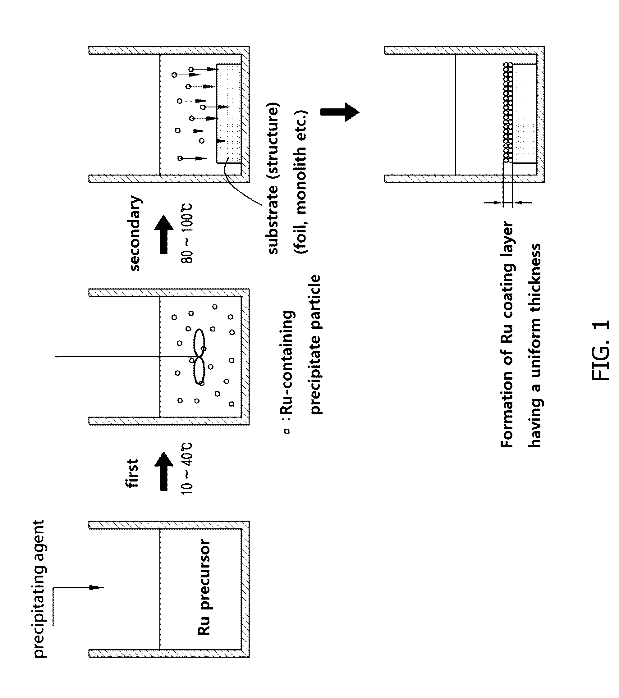
[0068]First, in the same manner as Korean Patent No. 1019234, a surface of an FeCr alloy foil, a metal substrate of a ferrochrome alloy material, was electrochemically treated at 5 V for 30 min and then heat-treated at 900° C. for 6 h to prepare the metal substrate for ruthenium coating wherein an alumina layer is uniformly formed as a carrier on the surface thereof.

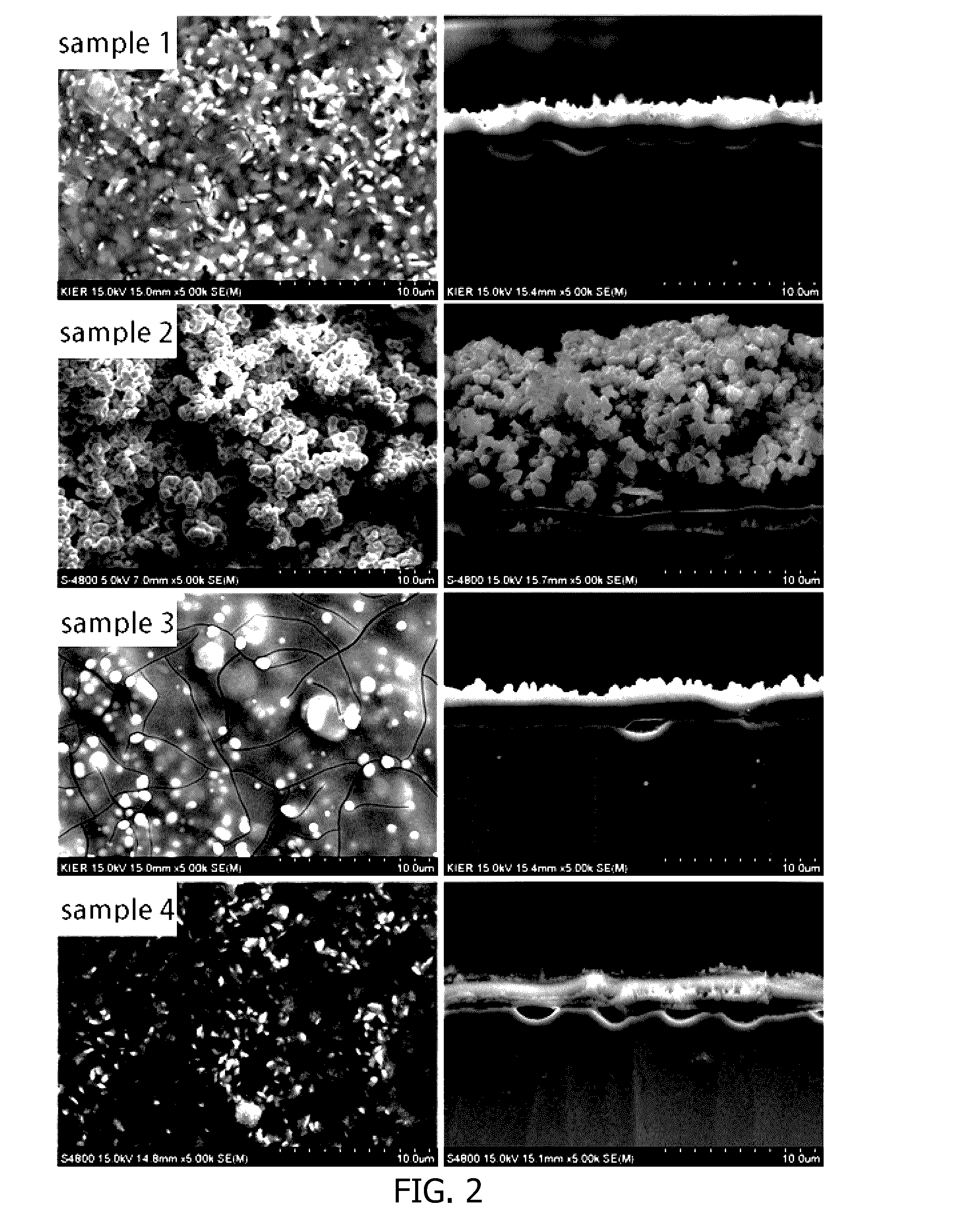
[0069]Ruthenium nitrosyl nitrate as a ruthenium precursor was mixed with distilled water to give a solution in the concentration of 230 mM. Different amounts of ammonia solution as a precipitating agent were added to the above solution to prepare Samples 1 to 4 having a pH of 6, 7, 8 and 11, respectively. After each of the solutions thus obtained was first aged by stirring at room temperature (25° C.) for 24 h, the FeCr alloy foil, a substrate as prepared above, was immersed in the above aged solution and secondar...

example 2

Analysis of Ruthenium Coating Layer Depending on the Aging Condition

[0085]Among the aging conditions, the time of the first aging and the temperature of the secondary aging were changed, and then the amount of Ru coated and the thickness of coating layer were measured, respectively.

[0086]In Samples 9 and 10, the precursor-containing precipitation reaction solutions of pH 7 were first aged at room temperature (25° C.) with stirring for 6 h and 12 h, respectively, whereas the secondary aging time was fixed to 48 h at 100° C.

[0087]In Samples 11 and 12, the precursor-containing precipitation reaction solutions of pH 7 were first aged at room temperature (25° C.) with stirring for a fixed time of 24 h, whereas the secondary aging was performed at 80° C. and 90° C., respectively, for 48 h.

[0088]The FeCr alloy foils coated with Ru, prepared by changing the stirring time and temperature, were ion-milled and cross sections thereof were analyzed, and SEM images are shown in FIG. 4.

[0089]From ...

experiment 1

Performance Evaluation of Ru / Al2O3 Pellet Catalyst Vs. Ru / Al2O3 Coated FeCr Alloy Monolith Catalyst

[0091]A Ru coating layer was formed on the surface of FeCr alloy monolith on which an alumina carrier was formed in advance according to the same procedure as Sample 2 of Example 1, except that the substrate had a monolith form, not a foil form.

[0092]Catalyst performance evaluation on the steam reforming reaction of natural gas was carried out against the above-obtained FeCr alloy monolith catalyst on which the Ru coating layer was formed (Ru / Al2O3 coated FeCr alloy monolith catalyst) under the following experimental conditions. Prior to the catalyst performance evaluation, the catalyst was reduced under a hydrogen atmosphere at 700° C. for 3 h.

[0093]For comparison, the Ru / Al2O3 pellet catalyst was also reduced under the same conditions and subjected to the catalyst performance evaluation under the following experimental conditions. Here, the Ru / Al2O3 pellet catalyst was obtained from ...


PUM

PropertyMeasurementUnit
Temperatureaaaaaaaaaa

Abstract

The present invention relates to a method for preparing a catalyst comprising a ruthenium-containing catalyst layer highly dispersed with a uniform thickness on a surface of a substrate having a structure, which comprises first aging a mixed solution of a ruthenium precursor-containing solution and a precipitating agent to form a ruthenium-containing precipitate seeds, secondarily aging the first aged mixed solution to grow the seeds thereby forming ruthenium-containing precipitate particles, and then contacting the particles with a substrate to deposit the particles on the surface of the substrate. Since the catalyst has a structure in which the round shaped ruthenium-containing precipitate particles are piled to form the ruthenium-containing catalyst layer, it has a large specific surface area. Thus, the catalyst may exhibit excellent catalytic performance in various reactions for producing hydrogen using a ruthenium catalyst.

Description

TECHNICAL FIELD[0001]The present invention relates to a method of preparing a catalyst comprising a ruthenium-containing catalyst layer formed on a surface of a substrate having a structure and a use of the catalyst prepared thereby.BACKGROUND[0002]In the conventional preparation of a metal substrate comprising a catalyst coating layer, the representative catalyst coating methods were an impregnation method, wherein the metal substrate is impregnated in a catalyst precursor solution to support the catalyst, and a washing coating method, wherein the metal surface is coated with a catalyst using a slurry solution which is a mixture of a powder catalyst, whose catalyst is supported by a carrier in advance, and an alumina sol.[0003]In achieving a certain amount of catalyst loading, the impregnation method has the problems of increase of number of impregnation and difficult control of dispersion of the active metal particles due to the low catalyst loading amount. Also, the washing coati...

Claims


Application Information

Patent Timeline
IPC IPC(8): B01J37/03B01J23/46C01B3/58B01J35/02C01B3/16B01J23/89B01J37/08
CPCB01J37/035B01J23/8993B01J23/462B01J37/08B01J35/023C01B3/16C01B2203/044C01B2203/0233C01B2203/0283C01B2203/1082C01B2203/1064C01B2203/047C01B3/583B01J37/031B01J37/10B01J37/342B82Y30/00C01B3/40Y02P20/52B01J35/30B01J35/23
Inventor KOO, KEE-YOUNGYOON, WANG-LAIJUNG, UN-HOHWANG, YOUNG-JAEEOM, HYUN JI
Owner KOREA INST OF ENERGY RES
Learn More