
Multi-wavelength laser rapid prototyping system and method

Inactive Publication Date: 2017-06-08
CHONGQING INST OF GREEN & INTELLIGENT TECH CHINESE ACADEMY OF SCI
View PDF7 Cites 16 Cited by
  • Summary
  • Abstract
  • Description
  • Claims
  • Application Information

AI Technical Summary

Benefits of technology

This patent is about a system and method that uses a short wavelength laser to melt materials and form structures. This improves manufacturing resolution and precision. Additionally, the system uses a dual-wavelength laser to simultaneously scan and improve manufacturing efficiency. The long wavelength laser is also used for preheating and heat treatment to reduce thermal stresses on the structures and reduce waste of powers.

Problems solved by technology

It will result in a large thermal stress in the manufactured structure, and cause structural deformation or even fracture.
However, high temperature in the chamber can also damage the powders outside the laser irradiated area, and reduce recovery utilization rate of powders.
However, three laser beams scanned one after one in this method, which need a complicated control procedure and more manufacturing time.
However, the preheating COS laser need to be projected at a large area for a long time in the method.
The energy utilization rate of the preheating laser is low and it may also result in the waste of materials in the irradiated area.

Method used


Image

  • Multi-wavelength laser rapid prototyping system and method
  • Multi-wavelength laser rapid prototyping system and method
  • Multi-wavelength laser rapid prototyping system and method

Examples


example 1

[0061]The present invention will now be described in detail with reference to FIGS. 1 and 3 by taking the multi-wavelength selective laser rapid prototyping of ZrO2-Al2O3 ceramic as an example. The selected ZrO2-Al2O3 ceramic powders are spherical powders having particle sizes from 30 μm to 60 μm.

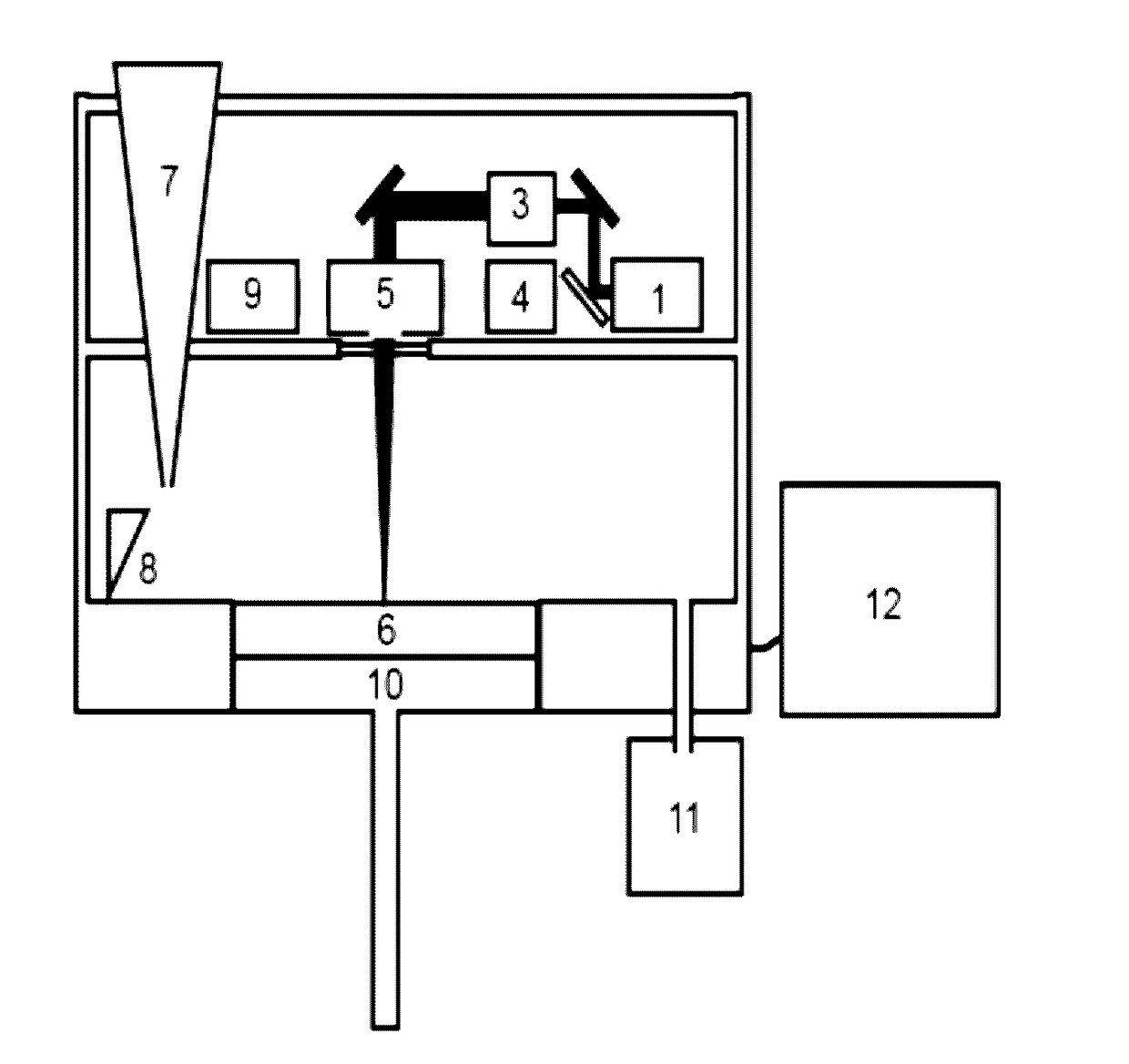
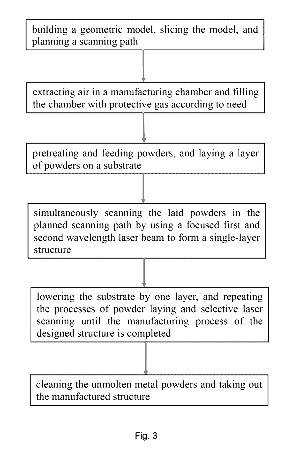
[0062]Firstly, a geometric model of ceramic structure is built by using a computer drawing software, the model is sliced, and the scanning path is planned. The air in manufacturing chamber is then extracted. The pretreatment and feeding of powders are carried out by the powder feeding components 7. A layer of ceramic powders is laid on substrate 7 by using the powder laying components 8. The thickness of the laid monolayer ceramic powders is 60 μm. A 532 nm laser beam outputted by a green light laser source 1 with a laser power of 50-150 W is selected as the first wavelength laser beam; and a 10.6 μm laser beam outputted by a CO2 laser source 2 with a laser power of 140-400 W is selected as...

example 2

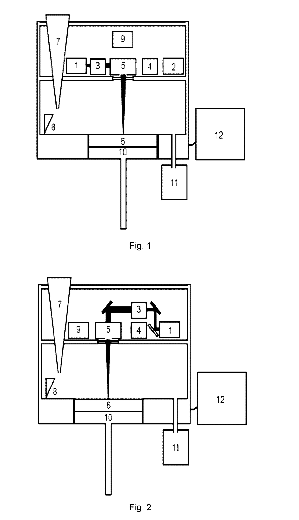
[0064]The present invention will now be described in detail with reference to FIGS. 2 and 3 by taking the multi-wavelength selective laser rapid prototyping of titanium alloy as an example. The selected titanium alloy powders are spherical powders having particle sizes from 20 μm to 30 μm.

[0065]Firstly, a geometric, model of titanium alloy structure is built by using a computer drawing software, the model is sliced, and the scanning path is planned. The air in manufacturing chamber is then extracted and filled with argon as a protective gas. The pretreatment and feeding of powders are carried out by the powder feeding components 7. A layer of titanium alloy powders is laid on substrate 7 by using the powder laying components 8. The thickness of the laid monolayer titanium alloy powders is 50 μm. As shown in FIG. 2, a 532 nm laser beam outputted by the light laser source 1 with a laser power of 30-50 W is selected as the first wavelength laser beam; and a 1064 nm laser beam outputted...


PUM

PropertyMeasurementUnit
Sizeaaaaaaaaaa
Sizeaaaaaaaaaa
Wavelengthaaaaaaaaaa

Abstract

This invention discloses a multi-wavelength selective laser rapid prototyping system comprising laser light sources, laser transmission and control components, laser focusing and scanning components, manufacturing chamber, powder feeding components, powder laying components, gas circulation control components, real-time monitoring components, lifting components, powder recovery components, and computer. Said laser light source comprises a first laser source for providing a first wavelength laser beam and a second laser source for providing a second wavelength laser beam, or a laser source for providing both the first and second wavelength laser beams. Adoption of a short wave laser beam in the system is beneficial to improve the manufacturing resolution and precision. At the same time a superposed long wavelength laser beam is adopted to ensure the preheating and subsequent heat treatment. Thermal stress of the manufactured structure is reduced. Manufacturing efficiency is further improved. A multi-wavelength selective laser rapid prototyping method is also provided.

Description

FIELD OF THE INVENTION[0001]The present invention relates to laser 3D printing technique, and more particularly to a multi-wavelength selective laser rapid prototyping system and method.DESCRIPTION OF THE RELATED ART[0002]3D printing is a typically digital and green intelligent manufacturing technology, in which three-dimensional complicated parts are directly fabricated layer by layer under computer control with the designed digital model. It has a wide range of applications in aerospace, defense industry, automobile, mold, consumer electronics, biomedical and other fields.[0003]Selective laser rapid prototyping is a high-precision 3D printing technology that can be used for the manufacture of parts with high precision and high complexity. At present, the selective laser rapid prototyping mainly includes selective laser sintering and selective laser melting. The typical energy sources for selective laser rapid prototyping are the 10.6 μm CO2 laser and the fiber laser or solid laser...

Claims


Application Information

Patent Timeline
IPC IPC(8): B29C67/00B28B1/00B33Y10/00B33Y30/00B23K26/70B28B17/00B23K26/06B23K26/082B23K26/342B22F3/105B33Y50/02
CPCB29C67/0077B22F3/105B28B1/001B33Y10/00B33Y30/00B33Y50/02B23K26/705B29C67/0088B28B17/0081B23K26/0604B23K26/0648B23K26/082B23K26/342B29C67/0085B29C67/04C04B35/64B29C64/153B29C64/277B29C64/268B29C64/393Y02P10/25B22F12/41B22F10/32B22F12/49B22F12/44B22F10/68B22F10/28B22F12/13B22F10/34B22F10/36B22F10/73B22F10/362B22F12/90Y02P10/20
Inventor DUAN, XUANMINGLIU, JIECAO, HONGZHONGFAN, SHUQIANZHENG, MEILINGLIU, JIQUAN
Owner CHONGQING INST OF GREEN & INTELLIGENT TECH CHINESE ACADEMY OF SCI
Features
  • Generate Ideas
  • Intellectual Property
  • Life Sciences
  • Materials
  • Tech Scout
  • Unparalleled Data Quality
  • Higher Quality Content
  • 60% Fewer Hallucinations
Learn More