
Temperature-compensated electronic apparatus

a technology of electronic equipment and compensation, applied in the direction of particle separator tube details, program control, instruments, etc., can solve the problems of inaccuracy of measurement and loss of ions, power loss, and temperature increase of semiconductor pn-junction or metal-semiconductor schottky junction of the diode, so as to improve heat spreading

Active Publication Date: 2018-02-15
THERMO FISHER SCI BREMEN
View PDF0 Cites 7 Cited by
  • Summary
  • Abstract
  • Description
  • Claims
  • Application Information

AI Technical Summary

Benefits of technology

The patent describes a temperature-controlled electronic apparatus that improves heat distribution and thermal management. The electronic components are arranged on a circuit board in a circular pattern, with increasing distance from a common center point. A temperature sensor measures temperature, and a control circuit regulates a heat-generating component to generate heat in response to the temperature measurement. This closed-loop control helps to achieve precise and stable operation of the electronic apparatus. The arrangement of the components also enhances accuracy and stability of an RF detector, which can provide a potential to an ion optical device. The apparatus includes a heat-generating component located at the center point of the paths, while the temperature sensor is located at the center point of the concentric circles. The heat-generating component may be a heating transistor mounted on a heat spreader that extends across the back side of the circuit board. The circuit board comprises multiple metal layers for better heat spreading and RF shielding. Overall, the invention improves performance and reliability of the electronic apparatus.

Problems solved by technology

Variation in the amplitude of the RF potential may affect the electric field to which the ions are subjected in the ion optical device, causing undesirable effects such as inaccurate measurements and loss of ions.
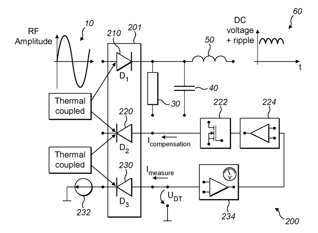
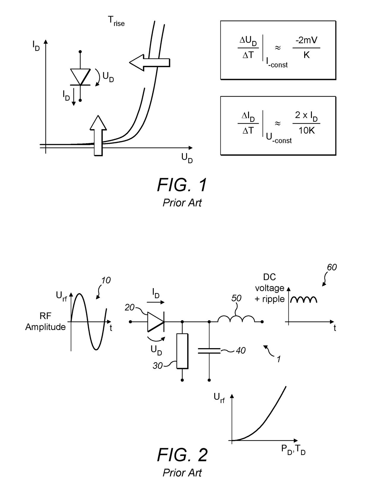
Every semiconductor has an intrinsic ohmic part (generally around 15-30Ω for a diode) in its current path, so some power loss will occur, even in normal operation.
A consequence of this power loss is that the semiconductor PN-junction or metal-semiconductor Schottky junction of the diode will increase in temperature.
Hence, temperature effects will cause a DC offset voltage error at the output 60 of the RF detector circuit.
This is particularly a problem when high power inputs are provided, such as for an RF potential to be provided to an ion optical device.
Firstly, the flow of heat through the circuit is non-uniform, making steady-state control difficult.
Furthermore, each resistor has its own tolerance, making the amount of heat generated difficult to set.
In view of Ohm's law and the formula for electrical power (P=I2R), a small change in current can cause a large change in the power dissipated and consequent heating effect.
This non-linear relationship makes control even trickier.
In some scenarios, controlling the circuit temperature in this way is less effective, particularly when high power input signals are provided.
The close proximity of the components makes the relationship even more unpredictable.
This makes the use of such ambient temperature compensation techniques to mitigate the self-heating effect very challenging.

Method used


Image

  • Temperature-compensated electronic apparatus
  • Temperature-compensated electronic apparatus
  • Temperature-compensated electronic apparatus

Examples


second embodiment

[0061]Referring to FIG. 7, there is illustrated an RF detector 300 in accordance with a Where components common with those of the RF detector 1 of FIG. 1 are shown, the same reference numerals have been used. The RF detector 300 comprises: a software controller 310; a diode 20; a resistor 30; a capacitor 40; and an inductor 50. The diode 20, resistor 30, capacitor 40 and inductor 50 operate in the same way as described above with respect to FIG. 1. The software controller 310 controls the way that signals are applied to the diode 20 for rectification and therefore the power dissipated in the diode 20. In principle, the software controller 310 controls the power dissipated in diode 20 to average (in an arithmetic sense) a fixed and constant level over time. In other words, the mean power dissipated over time remains fixed. This is achieved by dissipating additional power in the diode during a dummy time period at regular intervals and will now be illustrated using examples.

[0062]Ref...

third embodiment

[0069]Referring to FIG. 11, there is depicted a block diagram of a thermal controller for an RF detector in accordance with a The thermal controller comprises: a temperature sensor 610; a temperature control circuit 620; a voltage divider 630; a heating transistor 640; and a constant current source 650. Thermal shielding 660 is ideally provided to couple the heating transistor 640 and the temperature sensor 610.

[0070]The temperature sensor 610 measures the temperature of the circuit and provides a temperature signal 615 indicative of this measurement to the temperature control circuit 620. The temperature control circuit 620 is configured to generate a control signal 625, which controls the operation of the heating transistor 640 accordingly. The temperature control circuit 620 achieves this by comparing the temperature signal 615 with a set temperature level 635, which is indicative of a desired stable operating temperature and is set by the voltage divider 630 and may therefore b...


PUM


Abstract

A temperature-controlled electronic apparatus, comprises: a circuit board; a plurality of electronic components, mounted on the circuit board in an arrangement to form at least one electronic circuit; a temperature sensor, configured to measure a temperature of the at least one electronic circuit; and a heat-generating component, configured to be controlled by a temperature control circuit, the temperature control circuit being configured to control an amount of heat generated by the heat-generating component in response to the temperature measured by the temperature sensor. The plurality of electronic components are arranged on the circuit board to lie on one of one or more paths, each path of the one or more paths being defined by a respective circle having a radius.

Description

TECHNICAL FIELD OF THE INVENTION[0001]The invention concerns a temperature-compensated electronic apparatus, which may form part of an RF detector for generating a DC level from a RF input signal. Such an RF detector is also provided, together with a control circuit for setting an amplitude of an RF potential for supplying to an electronic amplifier in an analytical instrument using this RF detector. The analytical instrument may be a mass spectrometer comprising an ion optical device, such as a quadrupole mass filter.BACKGROUND TO THE INVENTION[0002]Techniques for converting an AC voltage to an equivalent DC voltage representing the amplitude of the AC voltage are well-known in many electrical or electronic systems. In the field of ion processing and mass spectrometry, a Radio Frequency (RF) detector uses such techniques to transform the RF voltage to a corresponding signal indicative of the amplitude of the RF voltage as a DC voltage, as part of a closed-loop control circuit to ma...

Claims


Application Information

Patent Timeline
IPC IPC(8): G05D23/32G05B19/048B32B37/06G05D23/19
CPCG05D23/32B32B37/06G05B19/048G05D23/1934G05B19/0426G05B2219/37431G05D23/1919G06F1/206H01J49/022H05K1/0201H05K7/20727
Inventor WOHLGETHAN, SVEN
Owner THERMO FISHER SCI BREMEN
Learn More