Lead-carbon metal composite material for electrodes of lead-acid batteries and method of synthesizing same

a lead-acid battery and metal composite material technology, applied in the field of battery industry, can solve the problems of extremely low solubility of carbon and the creation of lead-carbon metal materials, and achieve the effects of increasing hardness and electrical conductivity of metallic lead-carbon composite materials, and low porosity

Inactive Publication Date: 2018-09-13
ELSHINA VARVARA ANDREEVNA
View PDF0 Cites 2 Cited by
  • Summary
  • Abstract
  • Description
  • Claims
  • Application Information

AI Technical Summary

Benefits of technology

[0007]The need to produce nanocomposites and lead alloys with carbon can be attributed to the need for creating the invention. It is assumed that to the aforementioned advantages of introducing carbon into the electrodes of a lead-acid battery, such as increasing capacity, preventing the formation of large lead sulphate agglomerates, it can be added that the use of lead-carbon metal electrodes would significantly improve the performance of the lead-acid battery for the reduction of the weight of the electrodes of the accumulator, increasing their electrical conductivity and electrochemical activity.
[0008]Another need in the use of lead-carbon metal electrodes is the expected increase in corrosion resistance of electrode materials; the carbon included in the alloy is not soluble in dilute sulfuric acid, which forms the basis of the sulfuric acid electrolyte in the accumulator. Therefore, it is expected that the use of lead-carbon metal material will prevent the destruction of current leads due to intergranular corrosion, which is characteristic of the currently used Pb—Ca, Pb—Sb, Pb—Sn alloys, which in turn will increase the service life of the lead-acid battery. Based on these prerequisites, a lead-carbon composite material is synthesized, which can be used to manufacture electrodes of lead-acid batteries.
[0011]The proposed method for producing a lead-carbon metal composite material (composite) is based on the direct chemical interaction of a carbide ion or atomic carbon from organic substances with lead or its alloys in a salt chloride and / or halide melt medium in a temperature range of 700-900° C. As a result, a synthesis of nano- and microparticles of carbon takes place in the molten lead matrix, and in one stage directly in molten lead without the need for a separate stage of synthesis and isolation of carbon nanomaterials. This significantly reduces the complexity and laboriousness of obtaining lead metal composites with a high carbon content.
[0012]The resulting lead-carbon composites are characterized by a uniform distribution of the carbon particles in the form of graphene layers or graphite crystals up to 10 nm to 100 μm in volume, which leads to high homogeneity of the properties of the composites. This method can be used to obtain gratings of lead accumulators of any shape and size, because the metal composite obtained by chemical interaction of the salt melt components with the molten lead can then be re-melted for mold casting or rolled using the classical technology without losing the original properties of the resulting composite.
[0014]The lower limit of the temperature range for the production of lead-carbon composite metal material −700° C., is determined from the melting temperature of halide salt electrolytes so that the entire volume of salts is guaranteed to be melted during the experiment and provides the molten lead with protection against oxidation by air oxygen. When the temperature rises above 900° C., a significant salt content is observed out the crucible, which worsens the environmental friendliness and process ability of the process.
[0016]A new technical result achieved by the claimed invention is to obtain a homogeneous, low porosity and increased hardness and electrical conductivity of metallic lead-carbon composite material that can be used as grids of lead-acid batteries.

Problems solved by technology

The main obstacle to the creation of lead-carbon metal materials is the extremely low solubility of carbon in lead.

Method used


Image

  • Lead-carbon metal composite material for electrodes of lead-acid batteries and method of synthesizing same
  • Lead-carbon metal composite material for electrodes of lead-acid batteries and method of synthesizing same
  • Lead-carbon metal composite material for electrodes of lead-acid batteries and method of synthesizing same

Examples


example 1

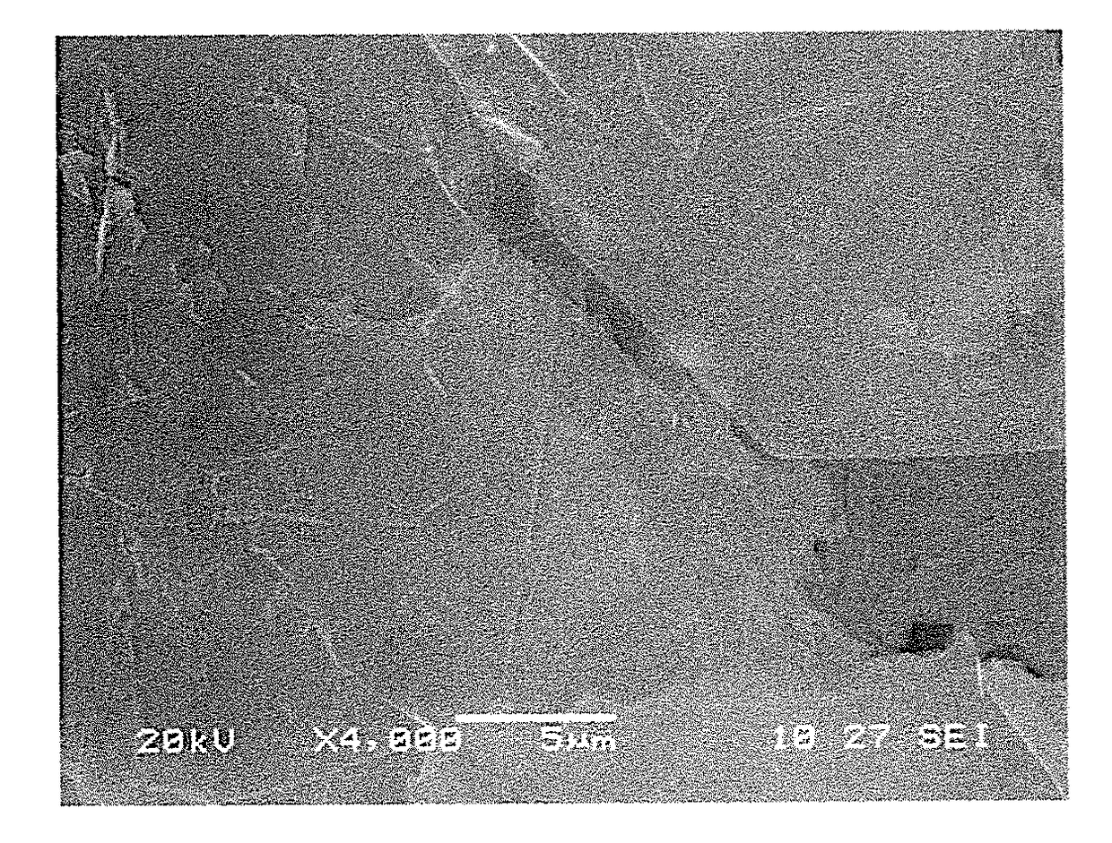
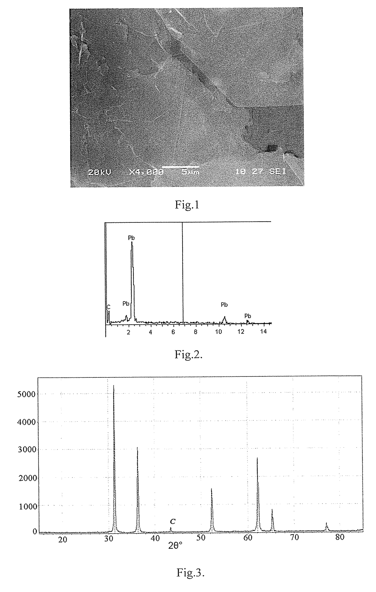
[0041]An alumina crucible was placed in a vertical heating furnace, 40 g of a dry mixture of lithium and potassium chlorides with potassium fluoride containing 15 g of tungsten carbide powder with a particle size of up to 50 μm were placed on its bottom. Over the carbide-containing salt mixture, lead pellets with a diameter of up to 5 mm with a purity of 99.9% by weight were placed onto which 10 g of a finely divided mixture of chlorides and fluorides of lithium and potassium were poured. After that, the furnace was heated to a temperature of 700° C. and held in an air atmosphere for 5 hours. At the same time, the carbide ion passed into the lead melt to form a lead-carbon composite. After high-temperature interaction, the lead-graphene composite was cooled at a rate of less than 0.1 deg / min.

[0042]In the cross-sectional image of the lead-carbon composite material shown in FIG. 1, it can be seen that the carbon formed inside the lead melt forms graphene layers 1 to 3 that are evenly ...

example 2

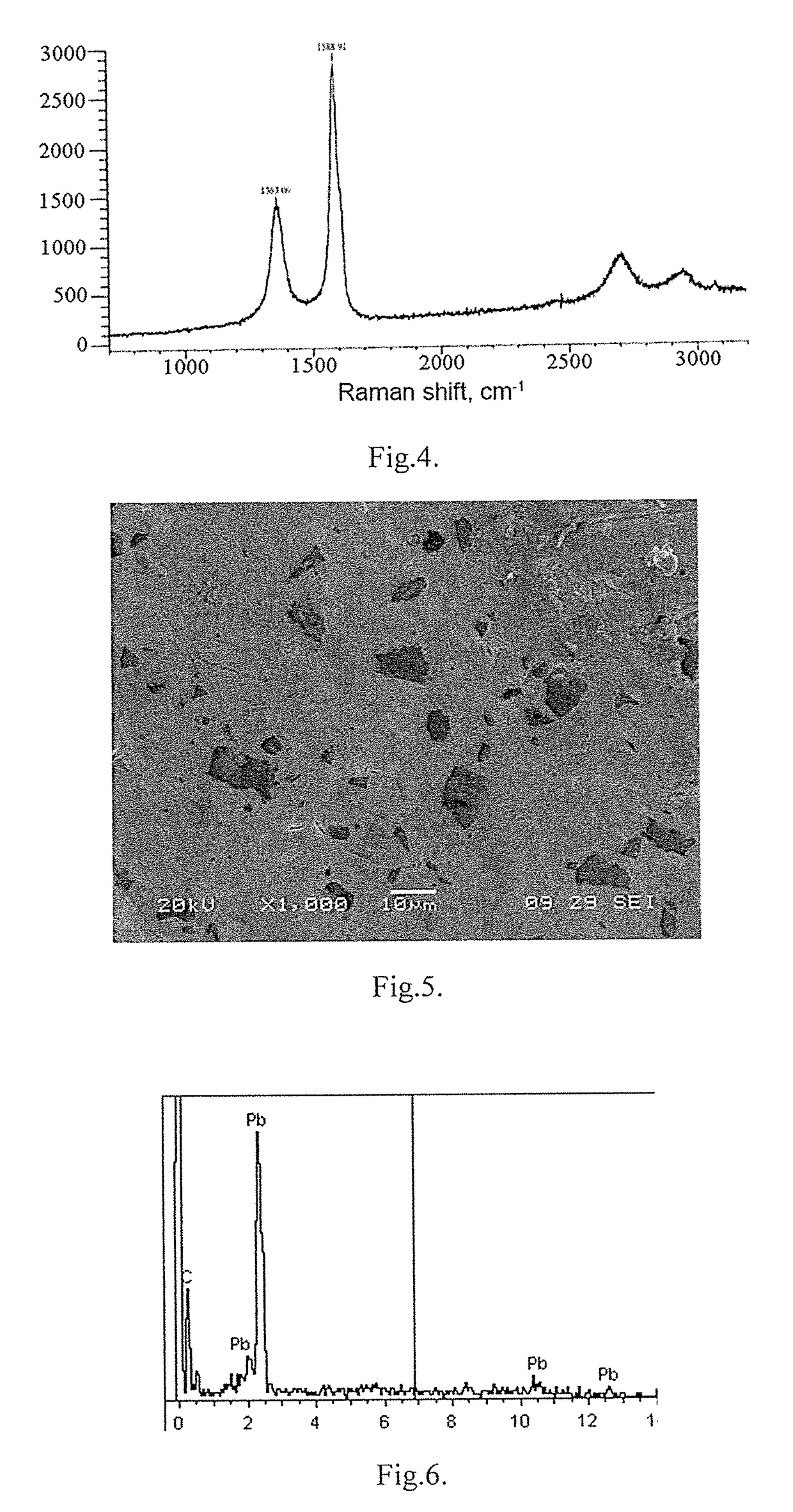
[0043]An alumina crucible was placed in the vertical heating furnace, 40 g of a dry mixture of chlorides, lithium, sodium, potassium, cesium containing 0.5 g of silicon carbide powder with a particle size of up to 100 μm were placed on its bottom. A disk of high purity lead was placed on top of the carbide-containing salt mixture, to which 10 g of the same finely divided salt mixture was poured, after which the furnace was heated to a temperature of 750° C. and held in an air atmosphere for 2 hours. In this case, the carbide ion passed into an aluminum melt with the formation of a lead-carbon composite. After high-temperature interaction, the lead-graphene composite was rapidly cooled in a water-cooled crucible. The cross-sectional image of the lead-carbon composite is shown in FIG. 5. The EDS spectroscopy data presented in FIG. 6 indicate the production of a lead-carbon composite with a content of 2.55 wt. % of carbon. In FIG. 7 shows the Raman spectrum of the carbon inclusion-grap...

example 3

[0044]An alumina crucible was placed in a vertical heating furnace, 40 g of a dry mixture of sodium, potassium, cesium chloride and ammonium fluoride containing 3.5 g of a tartaric acid powder were placed on its bottom. Over the carbon-containing salt mixture, granules of lead alloy Cl were placed on which 10 g of the same finely divided salt mixture were poured. After that, the furnace was heated to a temperature of 800° C. and held in an air atmosphere for 1 hour. In this case, the carbide ion passed into the lead melt to form a lead-carbon composite. After high-temperature interaction, the lead-graphene composite was cooled together with the furnace. The cross-sectional image of the lead-carbon composite material is shown in FIG. 8. The EDS spectroscopy data presented in FIG. 9 indicate the production of a lead-carbon composite with a content of 1.28 wt. % of carbon. In FIG. 10 shows the Raman spectrum of carbon inclusion—graphene.

[0045]The resulting composites are a typical meta...


PUM

PropertyMeasurementUnit
temperatureaaaaaaaaaa
particle sizeaaaaaaaaaa
pressureaaaaaaaaaa

Abstract

The invention is directed to a radical improvement of the specific electrochemical and corrosive characteristics of a lead-acid battery without a drastic change in the process of battery producing. The lead-carbon metal composite material contains from 0.1 to 10% by weight of carbon, lead is the remainder, while the structure of the material contains carbon allotropic modifications from graphene to graphite. The method for material synthesizing is characterized in that lead or its alloys are melted in a melt of alkaline and / or alkaline earth metal halides containing from 1 to 20 wt. % of metal carbides or non-metals with a particle size of 100 nm to 200 μm, or solid organic substances, for 1-5 hours at a temperature of 700-900° C.

Description

TECHNICAL FIELD[0001]The invention relates to the battery industry and can be used, in particular, as a new class of lead-carbon metal composite material for manufacturing current collectors used in lead-acid batteries.BACKGROUND OF THE INVENTION[0002]Carbon materials have been widely used in recent years as additives to the cathode and anode materials of lead-acid batteries (PT Moseley, J. Power Sources 191 (2009) 134-138) [1], K. Nakamura, M. Shiomi, K. Takahashi , M. Tsubota, J. Power Sources 59 (1996) 153-1572) [2]. The mechanism of the favorable effect of carbon on the electrochemical behavior of lead-acid battery electrodes has not yet been fully investigated, but there are suggestions that carbon increases the capacity of the lead-acid battery (P. Simon, Y. Gogotsi, Nat. Mater. 7 (2008)) 845-854) [3]. Carbon can also serve as a secondary phase preventing the growth of lead sulfate crystallites and not allowing particles to agglomerate to larger objects (D. Pavlov, P. Nikolov....

Claims


Application Information

Patent Timeline
Patent Type & Authority Applications(United States)
IPC IPC(8): H01M4/16H01M10/06C01G21/14H01M4/583
CPCH01M4/16H01M10/06C01G21/14H01M4/583H01M2004/027H01M2004/028C01P2004/61B82Y30/00C01G21/00C01G21/20C01P2002/72C01P2002/82C01P2002/85C01P2002/88C01P2004/03C01P2006/40C22C1/00C22C11/00C22C32/0084H01M4/661H01M4/68H01M4/73Y02E60/10H01M4/14
Inventor ELSHINA, LIUDMILA AVGUSTOVNAELSHIN, ANDREY NIKOLAEVICH
Owner ELSHINA VARVARA ANDREEVNA
Why Eureka
Try Eureka