
Self-powered microfluidic chip with micro-patterned reagents

Inactive Publication Date: 2018-10-18
RGT UNIV OF CALIFORNIA
View PDF0 Cites 2 Cited by
  • Summary
  • Abstract
  • Description
  • Claims
  • Application Information

AI Technical Summary

Benefits of technology

The technology described in this patent is a portable and low-cost microfluidic chip that can detect nucleic acids with high accuracy. The chip is designed to work in low-resource settings with no infrastructure or medical personnel. It can be used for monitoring HIV viral load, detecting MRSA infection, and screening for multiple pathogens on the same chip. The chip uses a vacuum battery system for precise fluid flow and can detect nucleic acids without separate sample preparation steps. The chip has various functionalities integrated into it, including reagent patterning, sample preparation and separations, and equipment-free micro-pumping. The chip uses isothermal amplification and digital detection, which is more robust and less affected by environmental variations than PCR. The chip can determine the original template concentration by counting the number of endpoint fluorescing compartments due to amplification.

Problems solved by technology

However, most diagnostic assays that are commercially available are qualitative, providing only positive / negative readouts, or require additional separate steps for DNA detection.
The current standard for quantitative testing is real-time PCR, a process that is not well suited for low-cost field operations.
Although this method is rapid, there are several drawbacks with inkjet printing.
First, the cost for specialized biological compatible inkjet printers can be very high and each service run can cost several thousands of dollars.
The cost of maintenance is also high with these devices since the costly print heads can be easily damaged, clogged or contaminated with the printed medium.
Second, the final shape and printed footprint depends strongly on the hydrophilicity of the substrate and the viscosity of the ink medium.
However, each pass needs to wait until the previous run is dry before performing the next run if a small footprint is desired.
Finally, inkjet printing often requires special buffers or solvents to control the viscosity of the printed liquid, which may not be compatible with subsequent biological reactions such as nucleic acid amplification.
As with inkjet printers, the robotic dispensers can be costly and not be part of a list of equipment that laboratories commonly possess.
The main drawback of this method is the lack of resolution in order to print reagents into microfluidic structures.
However, other methods such as capillary printing, microfluidic networks, evaporation, or degas based printing all create continuous-shaped patterns defined by the fluidic channels, which make it difficult or impossible to pattern inside the confinement of microwells.

Method used


Image

  • Self-powered microfluidic chip with micro-patterned reagents
  • Self-powered microfluidic chip with micro-patterned reagents
  • Self-powered microfluidic chip with micro-patterned reagents

Examples


example 1

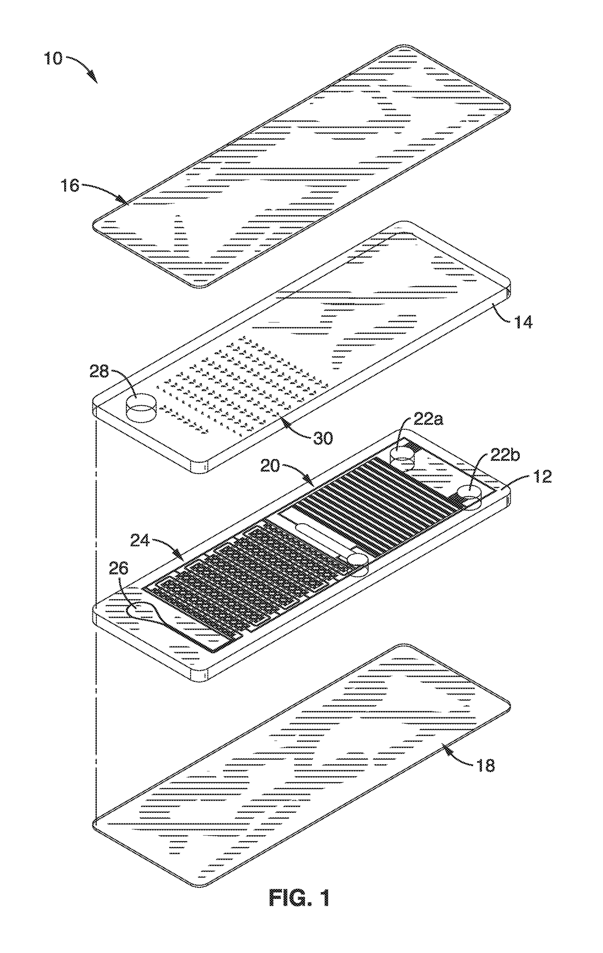
[0086]In order to demonstrate the apparatus and methods, a microfluidic chip platform was fabricated and tested. The chips were fabricated using a standard soft lithography process. Generally, the bottom 3 mm PDMS fluidic layers were made by casting PDMS on a silicon wafer that had protruding microfluidic channels created from photo-patterned (OAI Series 200 Aligner) SU-8 photoresist (Microchem). The main fluid and vacuum channels were 300 μm in height. The microcliff gaps were formed with heights of 40 μm, 120 μm, 170 μm, 240 μm and 300 μm for evaluation. A waste reservoir was created with a 5 mm puncher. The vacuum battery void was fabricated by simply punching the bottom 3 mm PDMS fluidic layer with through holes. Different diameters of punchers (Harris Uni-Core, Ted Pella) were used to fabricate the desired vacuum battery volumes. A separate top blank piece of 3 mm PDMS was bonded on the top side to seal the fluidic layer by oxygen plasma bonding using a reactive ion etching mac...

example 2

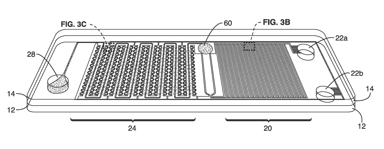
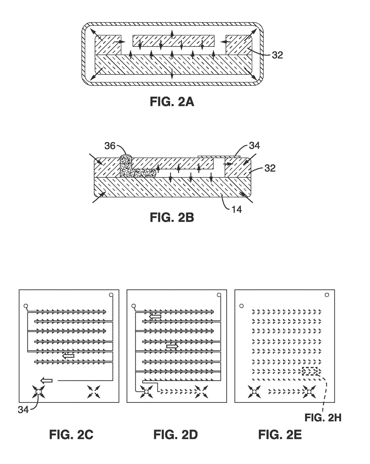
[0092]Functional testing of the chip designs was conducted to demonstrate digital plasma separations, hemolysis and isothermal digital amplification. The digital plasma separation design (FIG. 3C) prepares the sample for digital amplification by simultaneously enabling (1) autonomous plasma separation and (2) autonomous sample compartmentalization. A microcliff structure (FIG. 3C) with a vertical side-wall and abrupt reduction in channel height facilitates plasma separation into the microwells. The microcliff skimmed plasma near the top of the microchannel into the wells while the blood cells sedimented in the main channel. Plasma was drawn into the microwells when the remaining air diffused across the air permeable PDMS wall into the auxiliary battery.

[0093]The flow field is described by the Navier-Stokes equation as the blood cells experience gravitational force and Stokes drag. Separation of the blood cells ensures that there is minimal optical obstruction of the fluorescence sig...

example 3

[0109]To demonstrate the methods for micro-patterning reagents, chip top sections were produced with a pattern of unconnected, concentrated, dot-shaped reagents that were configured to be aligned with micro-wells in the bottom section of the chip. One important aspect of patterning is the ability to pattern reagents to be disposed inside of microwells. Conventional low cost printing methods all create continuous-shaped patterns defined by the fluidic channels, which make it difficult or impossible to pattern inside the confinement of microwells. The small footprint avoids bonding problems and also avoids reagent contamination in undesired areas. In this illustration, it was necessary to confine the reagents in the microwells, otherwise, unwanted nucleic acid amplification may occur and create false positive signals.

[0110]In this example, the printing method, termed “digital micro-patterning,” is used to pattern magnesium acetate, an amplification initiator for isothermal nucleic aci...


PUM

PropertyMeasurementUnit
Flow rateaaaaaaaaaa
Volumeaaaaaaaaaa
Shapeaaaaaaaaaa

Abstract

A microfluidic apparatus and methods for fabrication with a fluidic layer and a pattern layer of spots of concentrated reagents that are disposed in wells of a fluidic layer when the two layers are bonded together. Reagents are stored on the chip prior to use. Because reagents are confined to specific wells, contamination of the channels and other microfluidic structures of the fluidic layer are avoided. The fluidic layer also has a system of vacuum channels and at least one vacuum void to store vacuum potential for controlled micro-fluidic pumping. The top and bottom surfaces of the bonded layers are sealed. The chip can be used for point of care diagnostic assays such as quantitative testing, digital nucleic acid amplification, and biochemical testing such as immunoassays and chemistry testing.

Description

CROSS-REFERENCE TO RELATED APPLICATIONS[0001]This application is a 35 U.S.C. § 111(a) continuation of PCT international application number PCT / US2016 / 056127 filed on Oct. 7, 2016, incorporated herein by reference in its entirety, which claims priority to, and the benefit of, U.S. provisional patent application Ser. No. 62 / 238,583 filed on Oct. 7, 2015, incorporated herein by reference in its entirety. Priority is claimed to each of the foregoing applications.[0002]The above-referenced PCT international application was published as PCT International Publication No. WO 2017 / 062864 on Apr. 13, 2017, which publication is incorporated herein by reference in its entirety.STATEMENT REGARDING FEDERALLY SPONSORED RESEARCH OR DEVELOPMENT[0003]Not ApplicableINCORPORATION-BY-REFERENCE OF COMPUTER PROGRAM APPENDIX[0004]Not ApplicableBACKGROUND1. Technical Field[0005]The present technology pertains generally to passive microfluidic diagnostic sensing systems, and more particularly to a Self-power...

Claims


Application Information

Patent Timeline
IPC IPC(8): B01L3/00B81B1/00B81C1/00
CPCB01L3/502707B01L3/50273B81B1/006B81C1/00119B01L2300/0816B01L2300/0864B01L2300/0883B01L2400/0487B01L2400/049B81B2201/05B81B2203/0338B81B2203/0315B01J2219/0043B01J2219/00619B01L2200/16
Inventor LEE, LUKE P.YEH, ERH-CHIA
Owner RGT UNIV OF CALIFORNIA
Learn More