Osmosis battery & high magnetic field generator & superconducting ionic current loop

a generator and high magnetic field technology, applied in the direction of machines/engines, semi-permeable membranes, electrolysis, etc., can solve the problems of stymies still ahead without hope, extreme cost, and serious challenges in sealing, mass transfer and maintenan

Inactive Publication Date: 2018-12-06
WEI YANMING
View PDF3 Cites 2 Cited by
  • Summary
  • Abstract
  • Description
  • Claims
  • Application Information

AI Technical Summary

Problems solved by technology

In January 2014, Statkraft terminated their osmosis project, because of many difficulties for scale-up, such as expensive membranes, silt and bacteria clog or contamination, cheaper competition from other renewable energy source, etc.
The carrier of osmotic pressure is usually aqueous solution, of course, it is never a decent choice to drive hydraulic motor, unless special complicated fluids interface adapting mechanism can be provided, but it will confront serious challenge in seal, mass transfer, and maintenance.
Unfortunately, awesome stymies are still ahead without hope to overcome in foreseeable short future, main Gordian knots are:
Detail intrinsic transient chemical reaction mechanism not yet totally understood, extreme costy metal platinum for catalyst, membranes not reliable, high pressure hydrogen gas storage.
Therefore, there is still a long long way to its commercialization and market acceptance.
Zero electric resistance is really perfect, but unfortunately it currently is not convenient and even not affordable to sustain the required cryogenic extreme cold working space.
Even a workable liquid-nitrogen-immersed superconductor wire can only carry couples to dozens of thousand amperes current, otherwise overload will disable superconductivity.
This still limits the bold applications with million amperes current huge demand.
Obviously, room temperature superconductor is the eventual objective, but the exploration path is definitely beset with rocks and brambles.
Although the theoretic first principles can guide the new material concoct, anyway, the trial-and-error is still the most used method, and it needs a long time to reach perfect.
Yes, I can build such one, but it is no longer the regular battery.
The chemical reaction can result in deterioration or damage even explosion if inappropriate use or bad maintenance, such as the typical irreversible sulfation in car battery.
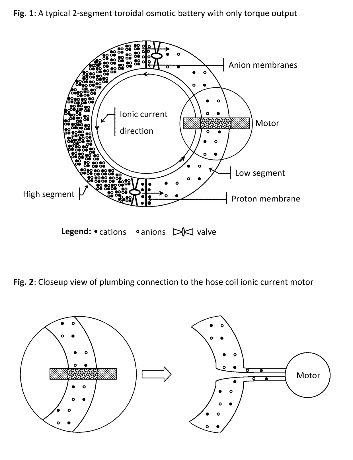
Of course, nobody can infuse hadrons into conductive wires of loads, then how can the loads get power from an isolated current loop without any terminal?
Therefore, such an ionic current loop special battery can only have immediate mechanic power output in best convenience, or like a wound spring coil as used in antique clock.
However, membranes area and rated flux, along with valve openness, can limit the mass flow.
Anyway, if the ambition to enlarge current is crippled, it is just an engineering issue, and the simplest method is to use large diameter pipe or add more membrane area.
In my humble opinion, it may be a wrong way by exploring special formulated superconductor materials, because even the electrons Cooper pairs in superconductors, are still less freedom than ions in solutions.
A short-circuited heavy duty battery may produce thousands amperes, but risks a lot, even explosion, definitely not recommend to do so, because of too much ohmic heat.
The science behind such an exotic motor is still controversial, though there have published tons of theses on it.
In real world, such a motor is absolutely useless, because it simply short-circuits power supply and draws remarkable current, even causing nasty heat and burning smell.
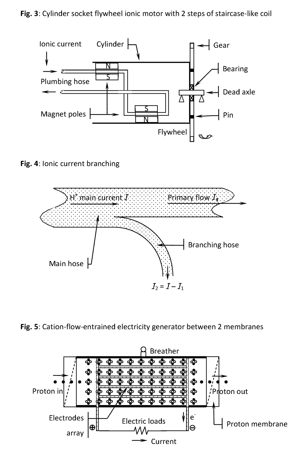
To replace the shaft of ball bearing motor with a section of pipe carrying ionic current in osmotic battery solution loop, and let iron flywheel slip on the pipe, the vast superconducting ionic current may also drive it, though efficiency is never decent.
Of course, this method does not work if inserting the plate in negative ion flow channel.
Therefore, this method may be not cheaper than a hooked generator, though its structure and installation are so simple.
Insertions in liquid need holes on tube wall with good seal for electric poles exposure, but if drilling then sealing job is not favored, then wrapping a copper foil around plastic tube may be workable too, though thick wall may reduce entrainment effect then result in low efficiency.
Of course, directly using golden pipe is more simple, but sadly too expensive.
It is well known that fast flowing water can result in serious water hammer effect if suddenly stopped inside pipe.
One switch is enough for a conventional electric circuit, but herein one valve may not be enough though it can cut off ions current in the loop, because ions flow need a complete loop to keep integrity and everywhere electric neutrality.
By paralleling super capacitor(s), it can receive the buffered energy in magnetic field for safe shutoff, but how to do so is tricky because of electrodeless feature.
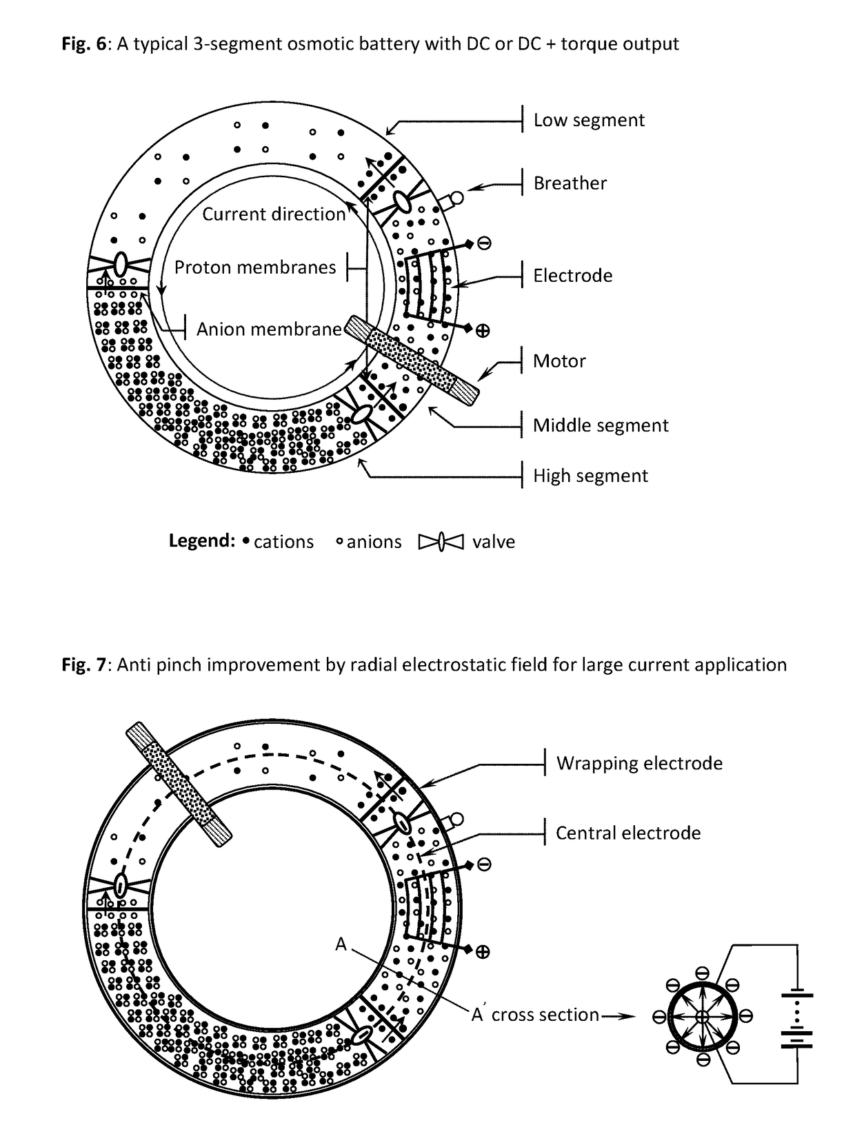
But, sustainable pinches are less researched.
If this osmotic battery is used in the same purpose, the pinch effect should be concerned, and obviously the ready theories for destructive pinches are not applicable.
Transversal stratification occurs too but potential explosion.
Even current large enough, but if cross section area also big enough, then current density can still be too small to exhibit pinch effect.
Although wire Z-pinch can be used to demo nuclear fusion, it seems still not feasible to deal with such one-time puff.
Behind the great record achievements, there always is unbelievable vast investment that even a small country is not affordable by her GDP.
My opinion: relying on special solid materials is probably not smart, as the reason is mentioned many times afore—“free electrons” in any conductor is not really free.
Although ripping off atoms' all electrons can be done by bombardment of high energy particles, however it is not a good bargain because electric field is always dissipative field.
This interdisciplinary research is complicated very much, and above theory disclosure is just a small portion of my full thought products.

Method used


Image

  • Osmosis battery & high magnetic field generator & superconducting ionic current loop
  • Osmosis battery & high magnetic field generator & superconducting ionic current loop
  • Osmosis battery & high magnetic field generator & superconducting ionic current loop

Examples


Embodiment Construction

[0185]With enough previous texts description on the subject inventions, it is time to graphizate or visualize typical or preferred embodiments. A drawing is worth of thousands words, isn't it?

[0186]1. The Simplest Osmotic Battery

[0187]FIG. 1 illustrates a 2-segment scheme with torque output only. To streamline ions flow, whole system is designed in toroidal shape though not mandatory. Every single segment is in semicircle appearance, one is just the afore-defined High Segment & supposed to hold high concentrated electrolytic solution, e.g. hydrochloric acid HCl, and another Low Segment to hold pure water. Both ends of 2 segments are docked together with proper membranes separation, one is protons exchange membrane, and another anions; 2 valves are also deployed near ends.

[0188]Although the membranes seem like circular disks or oblong screens, in fact, in most large embodiments, this drawing sketch can not reflect the real implementation, instead, available membranes are fabricated i...


PUM


Abstract

It is a battery, but electricity output not from electrochemistry, only ionic current loop and its induced high magnetic field ready for use. The power comes from osmotic pressure without any chemical reaction. Recharging the battery can be done by reverse osmosis, or replacement of liquid media. Electrolyte, 2 or 3 liquid segments, ion-exchange membranes and valves are needed. Only 3-segment system can output electricity by non-electrochemical method. Huge current can be generated in liquid-loop comprising different concentration compartments; it is not the regular invisible lepton electronic current, but pure hadron or baryon ionic current, up to millions amperes that can be far larger than any superconductor's capability. Protons and small anions are preferred, so as to reduce mass transfer & ion hammer effect.

Description

THE SCIENCE BEHIND SUBJECT INVENTIONS AND PRIOR ARTS[0001]Big idea needs big science![0002]1. Osmosis Pressure & Energy Density[0003]The natural process known as osmosis was first discovered as early as back in 1748 by Jean-Antoine Nollet. Another one century later, in 1885, the first winner of the Nobel Prize in Chemistry, Jacobs Henricus Van't Hoff contributed the osmotic pressure equation that is similar with the colligative gas state equation: π=iMRT, where π is osmotic pressure, i—ion factor, M—concentration in molarity (moles per liter), R—gas constant, T—temperature.[0004]As an example, for the regular sea water, at normal temperature, its osmotic pressure equals to 2*0.55*0.0821*300=27 atmospheric pressure. This significant pressure means that the river water can pump sea water 270 meter high by natural osmosis![0005]As to the energy density, just first exam the equivalence of pressure dimension:[0006]Pascal=Newtons per square meter=N / M2=NM / m3=J / m3=Joules per cubic meter.[00...

Claims


Application Information

Patent Timeline
Patent Type & Authority Applications(United States)
IPC IPC(8): B01D61/02B01D61/06B01D61/10F03G7/04B01D61/42
CPCB01D61/025B01D61/06B01D61/10F03G7/04B01D61/42B01D61/08F03G7/005
Inventor WEI, YANMING
Owner WEI YANMING
Why Eureka
Try Eureka