Inverse opal material for visible-light-driven photocatalytic degradation of organic pollutants, and preparation method thereof

Active Publication Date: 2018-12-06
SUZHOU UNIV
View PDF1 Cites 2 Cited by
  • Summary
  • Abstract
  • Description
  • Claims
  • Application Information

AI Technical Summary

Benefits of technology

[0005]The purpose of the present invention is to provide inverse opal material for visible-light-driven photocatalyt

Problems solved by technology

Throughout the world, about 12% of the dyes used are lost in their processing and handling operations.
Of which, 20% pass through wastewater into the environment, resulting in pollution of the water environment.
It can be seen that dye wastewater seriously endangers the water environment.
These dyes are usually biologically toxic and carcinogenic, and difficult to degrade by micro

Method used


Image

  • Inverse opal material for visible-light-driven photocatalytic degradation of organic pollutants, and preparation method thereof
  • Inverse opal material for visible-light-driven photocatalytic degradation of organic pollutants, and preparation method thereof
  • Inverse opal material for visible-light-driven photocatalytic degradation of organic pollutants, and preparation method thereof

Examples


embodiment 1

Nitrogen-Doped TiO2 Inverse Opal (N—TiO2 IO)

[0022]0.25 g diethanolamine was dissolved in 15 g anhydrous ethanol, followed by continuous stirring for 20 min. Then, 0.5 g tetrabutyl titanate was added to the mixture, and the mixture was indexed as A solution. Subsequently, 0.29 g urea was added to 30 mL anhydrous ethanol, and the solution was denoted as B solution. Then, 1 mL A solution and 1 mL B solution were mixed homogeneously. The PS opals were immersed into the mixed solution and dried at 60° C. Finally, the PS templates were removed via calcination in air at 500° C. at a heating rate of 1° C. min−1 for 2 h, and N—TiO2 IO was obtained.

embodiment 2

Nitrogen-Doped TiO2 Inverse Opal (N—TiO2 IO)

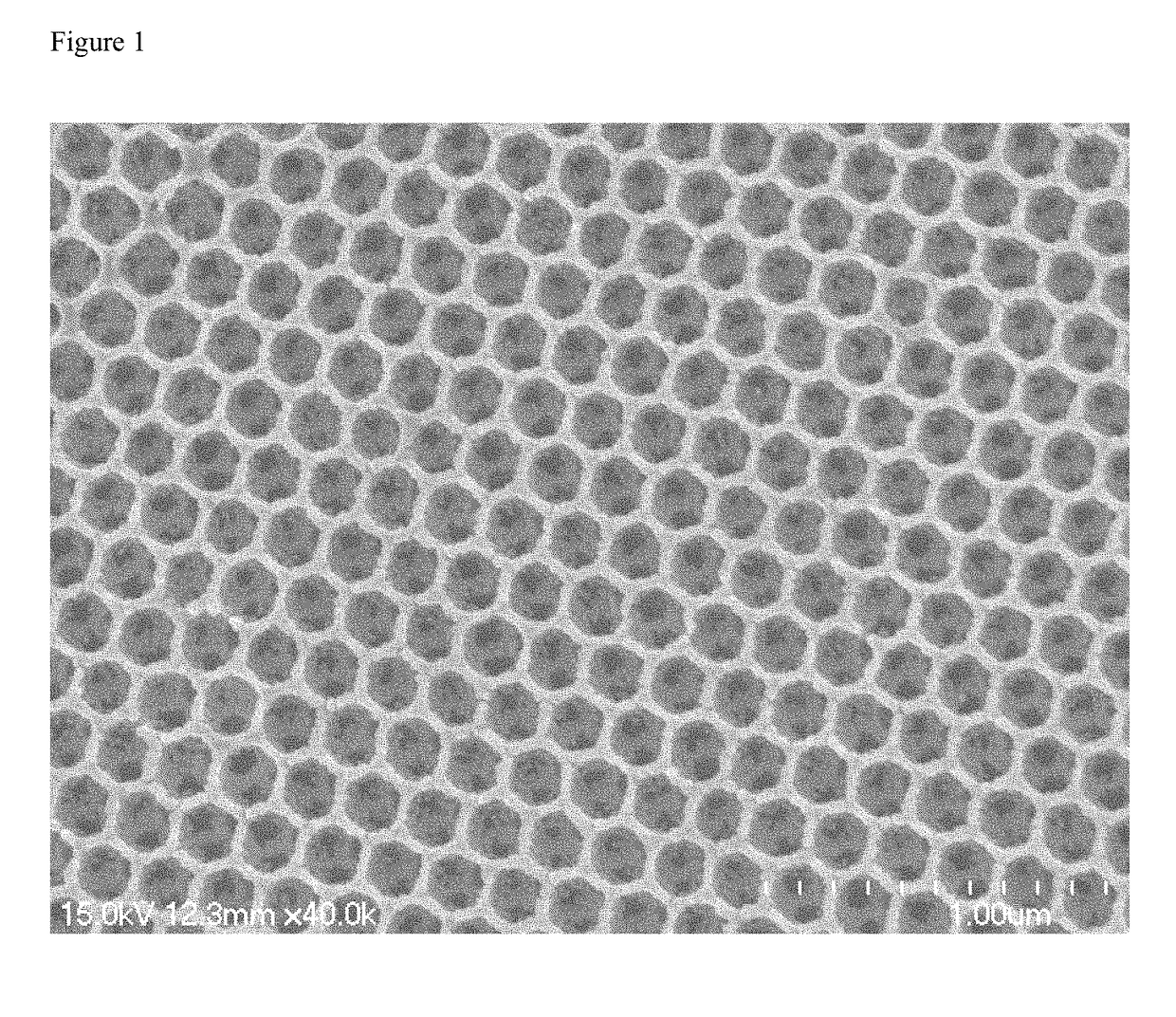
[0023]0.125 g acetylacetone was dissolved in 17.5 g anhydrous ethanol, followed by continuous stirring for 10 min. Then, 0.5 g tetrabutyl titanate was added to the mixture, and the mixture was indexed as A solution. Subsequently, 0.29 g urea was added to 30 mL anhydrous ethanol, and the solution was denoted as B solution. Then, 1 mL A solution and 1 mL B solution were mixed homogeneously. The PS opals were immersed into the mixed solution and dried at 60° C. Finally, the PS templates were removed via calcination in air at 500° C. at a heating rate of 1° C. min−1 for 2 h, and N—TiO2 IO was obtained. As can be seen in FIG. 1, N—TiO2 IO presents a face centered cubic arrangement with uniform pores.

embodiment 3

Nitrogen-Doped and CdSe-Sensitized TiO2 Inverse Opal (CdSe / N—TiO2 IO)

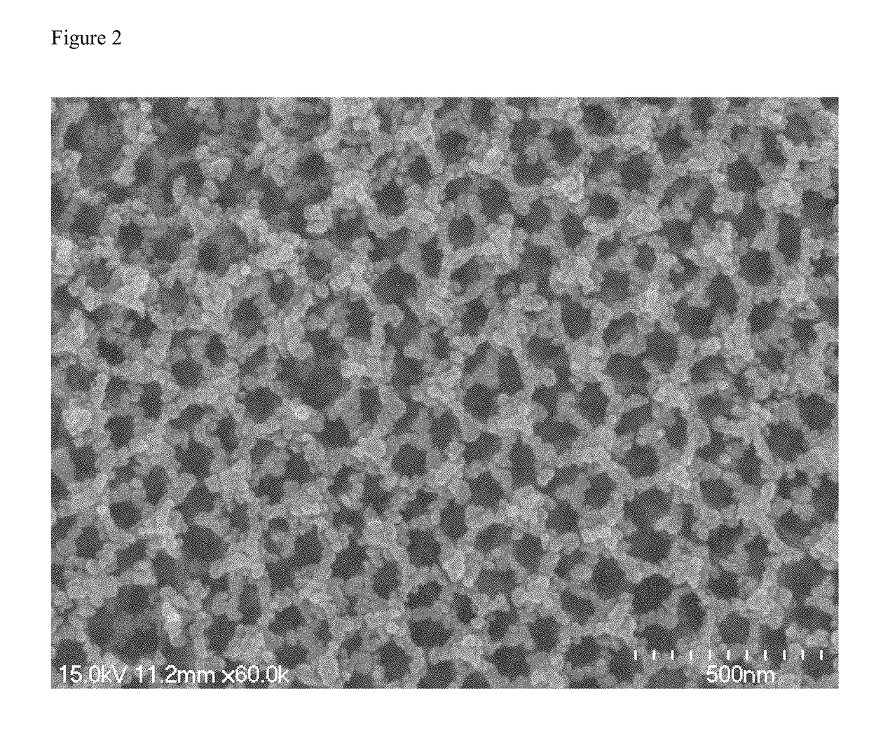
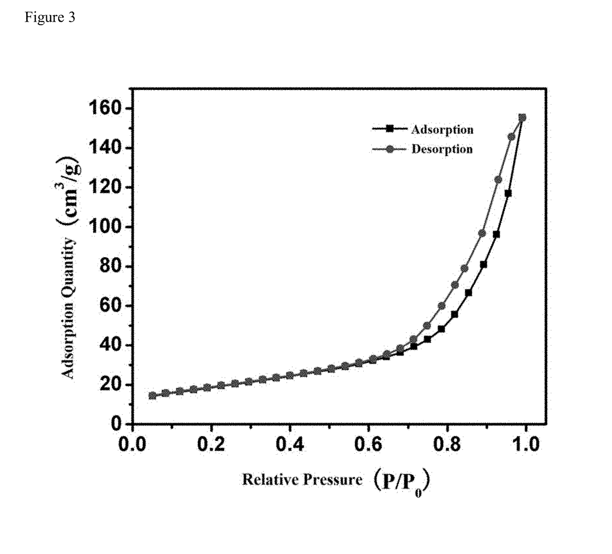
[0024]0.1830 g CdCl2, 0.0796 g Se and 0.2520 g Na2SO3 were added to 35 mL deionized water. After vigorously stirring at 3000 rpm, the suspension was transferred into a 50 mL Teflon-lined stainless-steel autoclave along with 20 mg N—TiO2 IO. The autoclave was heated to 180° C. for 8 h. After naturally cooling to room temperature, the FTO glass coated with N-doped and CdSe-sensitized TiO2 inverse opals (CdSe / N—TiO2 IO) was collected and washed with deionized water. As can be seen in FIG. 2, well-ordered inverse opals were retained after the hydrothermal process and a homogeneous coverage of CdSe can be observed without pore clogging. As can be seen in FIG. 3, the isotherms are identified as type III isotherms. The adsorption quantity is low in low specific pressure region, and the higher the relative pressure, the more adsorption quantity.


PUM

PropertyMeasurementUnit
Temperatureaaaaaaaaaa

Abstract

A preparation method of inverse opal material for visible-light-driven photocatalytic degradation of organic pollutants includes 1) using titanium dioxide precursor as raw material, preparing nitrogen-doped titanium dioxide inverse opal by one-step process in the presence of nitrogen source, and 2) in the presence of reducing agent, using the nitrogen-doped titanium dioxide inverse opal, selenium precursor, and cadmium precursor as raw materials to prepare the cadmium selenide sensitized nitrogen-doped titanium dioxide inverse opal.

Description

FIELD OF THE INVENTION[0001]The present invention belongs to the technical field of inorganic composite materials, particularly relates to an inverse opal material for visible photocatalytic degradation of organic pollutants and its preparation method, which can effectively remove the dyes in the water.TECHNICAL BACKGROUND[0002]With the development of science and technology, dyes are closely related to human daily life. Today, synthetic dyes are widely used in food, printing and dyeing, cosmetics and pharmaceutical industries. Throughout the world, about 12% of the dyes used are lost in their processing and handling operations. Of which, 20% pass through wastewater into the environment, resulting in pollution of the water environment. It can be seen that dye wastewater seriously endangers the water environment. These dyes are usually biologically toxic and carcinogenic, and difficult to degrade by microorganisms in the environment. Therefore, the search for cheap, efficient and ener...

Claims


Application Information

Patent Timeline
IPC IPC(8): C01G23/047B01J35/00B01J37/03B01J37/16C30B7/14C30B7/08
CPCC01G23/047B01J35/004B01J37/035B01J37/16C30B7/14C30B7/08B01J21/063C02F1/30C02F2101/308C02F2305/10B82Y20/00B01J27/24Y02W10/37C01G23/053C01G23/08C01P2002/52C01P2002/54C01P2004/03C30B29/16C30B29/60B82Y40/00
Inventor LU, JIANMEILI, NAJUN
Owner SUZHOU UNIV
Why Eureka
Try Eureka