
Processes and systems for reforming of methane and light hydrocarbons to liquid hydrocarbon fuels

a technology of liquid hydrocarbon fuel and process, which is applied in the direction of gaseous fuel, hydrocarbon oil treatment product, separation process, etc., can solve the problems of problematic transportation of such components to conventional brick and mortar production facilities, and achieves the effects of improving the overall thermodynamics of the process, reducing endothermicity (h) and the required energy input, and high activity

Active Publication Date: 2019-05-16
GAS TECH INST
View PDF13 Cites 3 Cited by
  • Summary
  • Abstract
  • Description
  • Claims
  • Application Information

AI Technical Summary

Benefits of technology

The invention describes a way to convert methane and other hydrocarbons to synthesis gas (H2 and CO) using carbon dioxide and steam. This process is more energy efficient and can be done at lower temperatures compared to traditional methods. The catalysts used in the process are tolerant to sulfur-bearing contaminants, so there is no need for expensive pretreatment of the feedstock. The resulting gas mixture is suitable for further processing to produce liquid hydrocarbons. The advantages of this technology include simplicity, cost savings, and flexibility for various applications.

Problems solved by technology

This results not only in cost savings, but also in the possibility of providing such overall processes in an easily transportable (e.g., skid mounted) configuration, which may be brought to sources of natural gas, or other sources of components of gaseous mixtures as described herein, from which sources the transport of such components to conventional brick and mortar production facilities would otherwise be problematic.

Method used


Image

  • Processes and systems for reforming of methane and light hydrocarbons to liquid hydrocarbon fuels
  • Processes and systems for reforming of methane and light hydrocarbons to liquid hydrocarbon fuels
  • Processes and systems for reforming of methane and light hydrocarbons to liquid hydrocarbon fuels

Examples


example 1

[0129]CO2-Steam Reforming Studies

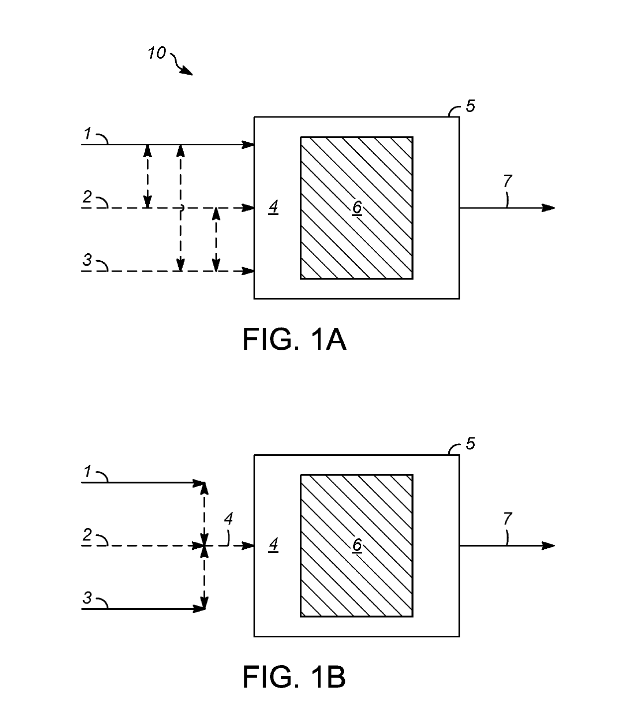
[0130]Pilot plant scale experiments were performed in which gaseous mixtures were fed continuously to a CO2-steam reforming reactor containing catalyst particles having a composition of 1 wt-% Pt and 1 wt-% Rh on a cerium oxide support. The performance of the system for CO2-steam reforming was tested at conditions of 0.7 hr−1 WHSV, 760° C. (1400° F.), and a gauge pressure ranging from 124 kPa (18 psig) to 172 kPa (25 psig). Two types of gaseous mixtures tested were (1) a composition containing methane, ethane, propane, and CO2, in addition to H2O, and simulating that obtained from the combined hydropyrolysis and hydroconversion of biomass (“Renewable Type”), and (2) a typical natural gas composition having a high level of CO2 (“Natural Gas Type”). The renewable type composition provided an example of a methane-containing feedstock that is also a “hydropyrolysis gaseous mixture,” as described above. The natural gas type composition provided an example...

example 2

[0132]Sulfur Tolerance of CO2-Steam Reforming Catalysts

[0133]Additional experiments were conducted in which a typical natural gas composition as described in Example 1 was subjected to CO2-steam reforming as also described in this example. However, the gaseous mixture or combined feed in this case was spiked with H2S at a concentration of 800 mol-ppm. Despite this high level of sulfur contamination, it was found that the offset in methane conversion was easily restored by increasing the reforming catalyst bed temperature from 760° C. (1400° F.) to 788° C. (1450° F.). Furthermore, the reforming catalyst surprisingly exhibited long-term stability over 400 operating hours (hours on stream) at this temperature, as well as the WHSV and pressure as described above with respect to Example 1. This stability, achieved despite the considerable sulfur concentration, was surprising in view of the sulfur sensitivity of conventional catalysts used for steam methane reforming.

example 3

[0134]Long-Term CO2-Steam Reforming Testing

[0135]The gaseous mixture described in Example 1 as the “Renewable Type” and having the composition provided in Table 1 was tested using the catalyst and conditions as described in Example 1, to evaluate performance of the system for CO2-steam reforming over an extended period of operation. The “Renewable Type” feed or gaseous mixture also provides an example of a representative “hydropyrolysis gaseous mixture” as described above. Long-term stability testing revealed that the composition of the synthesis gas product obtained was stable over 500 hours of operation under these constant conditions, demonstrating essentially no deactivation, over the extended operating period, of the reforming catalyst. FIG. 10 illustrates the stable synthesis gas product composition obtained over this operating period, with a high level of conversion of methane. FIG. 11 illustrates the stable molar H2 / CO ratio of the synthesis gas product obtained, which was n...


PUM

PropertyMeasurementUnit
temperatureaaaaaaaaaa
pressureaaaaaaaaaa
temperatureaaaaaaaaaa

Abstract

Processes for converting methane and / or other hydrocarbons to synthesis gas (i.e., a gaseous mixture comprising H2 and CO) are disclosed, in which at least a portion of the hydrocarbon(s) is reacted with CO2. At least a second portion of the methane may be reacted with H2O (steam), thereby improving overall thermodynamics of the process, in terms of reducing endothermicity (ΔH) and the required energy input, compared to “pure” dry reforming in which no H2O is present. Such dry reforming (reaction with CO2 only) or CO2-steam reforming (reaction with both CO2 and steam) processes are advantageously integrated with Fischer-Tropsch synthesis to yield liquid hydrocarbon fuels. Further integration may involve the use of a downstream finishing stage involving hydroisomerization to remove FT wax. Yet other integration options involve the use of combined CO2-steam reforming and FT synthesis stages (optionally with finishing) for producing liquid fuels from gas streams generated in a number of possible processes, including the hydropyrolysis of biomass.

Description

STATEMENT REGARDING FEDERALLY SPONSORED RESEARCH OR DEVELOPMENT[0001]This invention was made with government support under U.S. Department of Energy Award DE-EE-0007009. The government has certain rights in the invention.FIELD OF THE INVENTION[0002]Aspects of the invention relate to reforming catalysts and processes for the reforming of methane and / or other hydrocarbons to produce a synthesis gas product comprising H2 and CO, with further downstream conversion to liquid hydrocarbons.DESCRIPTION OF RELATED ART[0003]The ongoing search for alternatives to crude oil, for the production of hydrocarbon fuels is increasingly driven by a number of factors. These include diminishing petroleum reserves, higher anticipated energy demands, and heightened concerns over greenhouse gas (GHG) emissions from sources of non-renewable carbon. In view of its abundance in natural gas reserves, as well as in gas streams obtained from biological sources (biogas), methane has become the focus of a number o...

Claims


Application Information

Patent Timeline
Patent Type & Authority Applications(United States)
IPC IPC(8): C10G50/00C10L3/08C07C1/12C07C1/04C07C5/13C07C9/04C10G47/32B01D3/14
CPCC10G50/00C10L3/08C07C1/12C07C1/04C07C5/13C07C9/04C10G47/32B01D3/143C10G2300/1025C01B32/50C10G2400/02C10G2400/04C10G2400/16C10G2400/08B01D3/06Y02E50/30
Inventor MARKER, TERRYLINCK, MARTIN B.WANGEROW, JIMORTIZ-TORAL, PEDRO
Owner GAS TECH INST
Learn More