Electric drive train and method for feeding an electric drive train
- Summary
- Abstract
- Description
- Claims
- Application Information
AI Technical Summary
Benefits of technology
Problems solved by technology
Method used
Image

Examples
first embodiment
FIG. 3
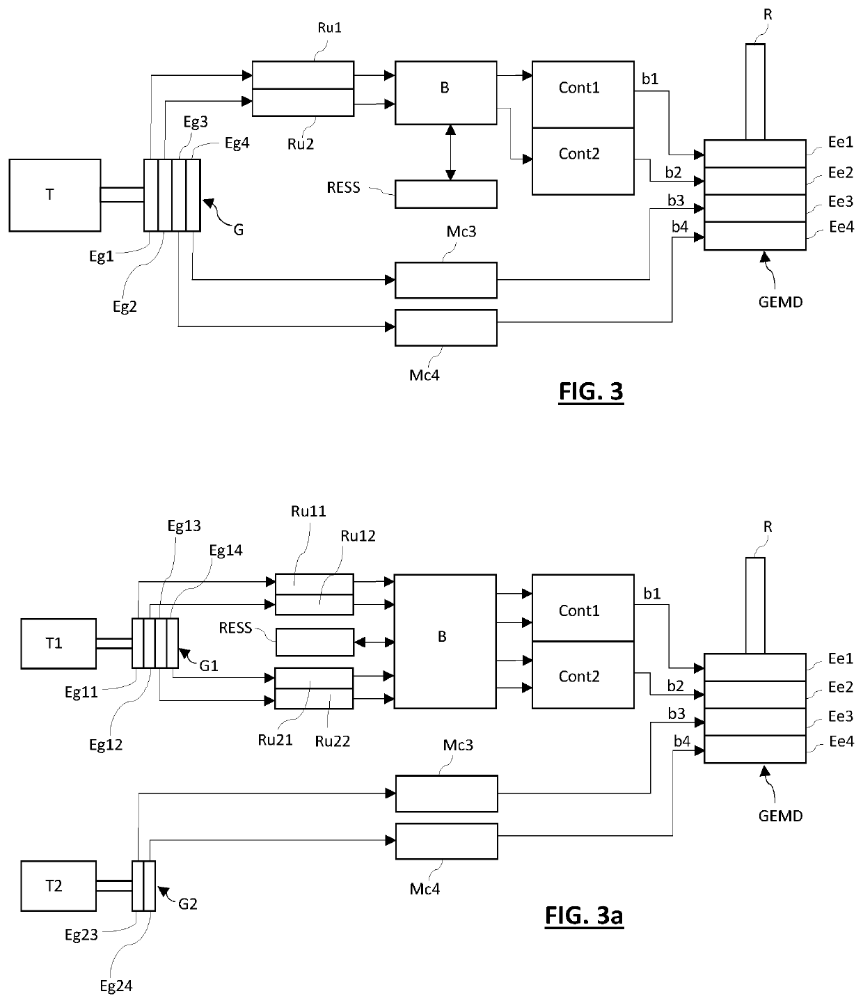
[0102]FIG. 3 presents a series-hybrid electric drive train architecture in accordance with an illustrative embodiment of the invention where a single engine T is used to power the notional four-stack electric motor assembly hereinafter referred as GEMD. This disclosed architecture uses the same multi-stack electric motor assembly GEMD and multi-stack electric generator assembly G as depicted in FIG. 2. The combination of the engine T and generator assembly G collectively represents a power source for the electric drive train.
[0103]A single engine T is used to power the electric motor assembly GEMD. In the electric drive train depicted in FIG. 3, a symmetrical four stack topology is used. It comprises the four stack electric generator assembly G as well as the four stack motor assembly GEMD.
[0104]A notable feature of multi stack architectures is that each motor element constituting the stack can be independently supplied by its dedicated controller assembly. Different topologie...
second embodiment
FIG. 3a
[0139]The disclosed invention can advantageously be applied to two twin engine aircrafts. The drawbacks inherent to conventional twin engine aircrafts have been previously exposed. Applying the disclosed architecture to the twin engine configuration improves both performances and safety during OEI transition as the RESS eliminates transient power lag. Additionally, significant economical advantages are brought by the disclosed configuration.
[0140]FIG. 3a presents a series-hybrid electric drive train architecture in accordance with another illustrative embodiment of the invention. This disclosed architecture uses the same multi-stack electric motor assembly GEMD as depicted in FIG. 2 and FIG. 3 and provides the same benefits and advantages of those depicted above in reference to said FIG. 3.
[0141]Two physically distinct engines T1 and T2 are used to power the notional four-stack drive GEMD, via the two completely independent pairs of power branches, b1-b2 and b3-b4. Each pair...
third embodiment
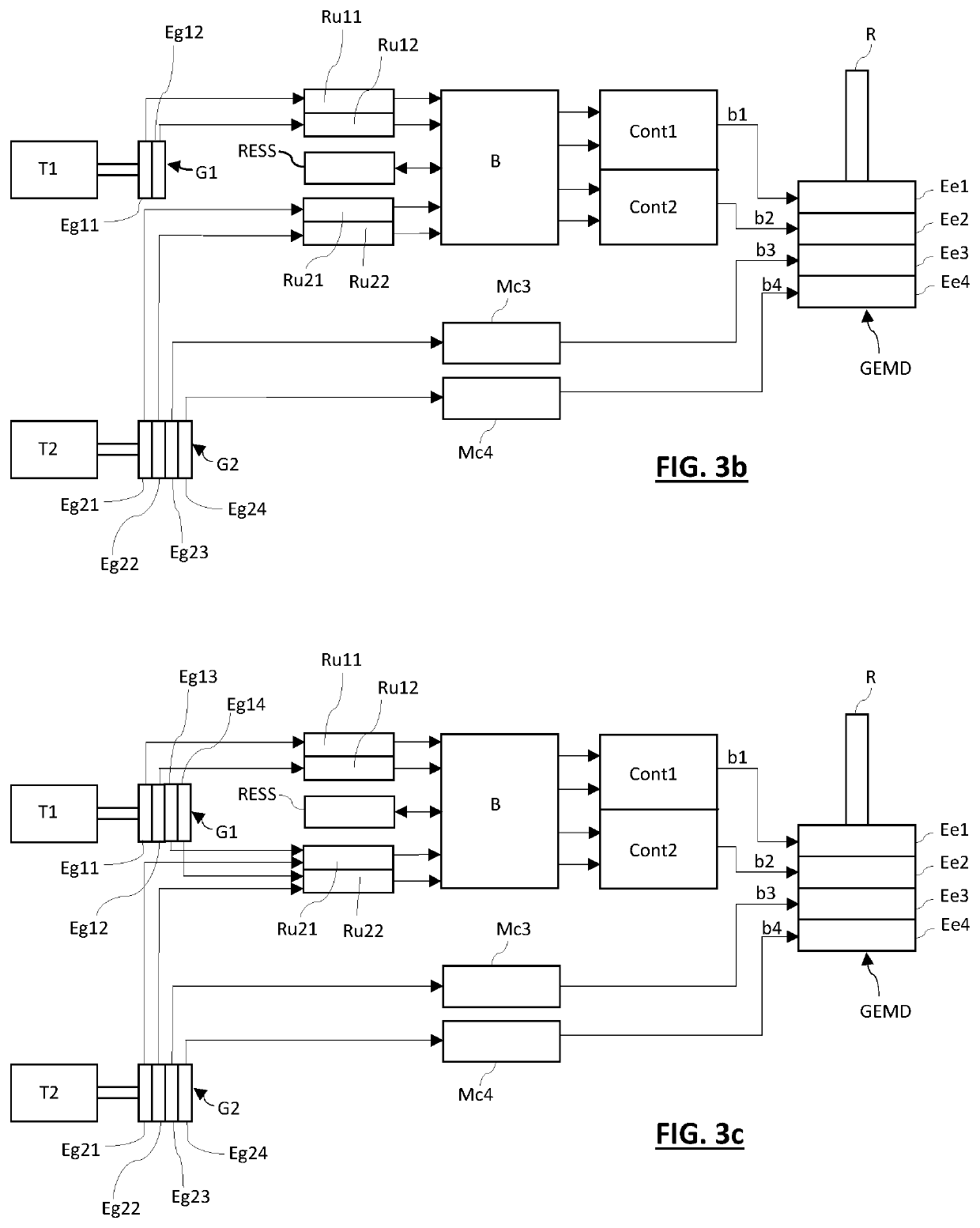
FIG. 3b
[0147]FIG. 3b presents a series-hybrid electric drive train architecture in accordance with yet another illustrative embodiment of the invention. The disclosed architecture uses the same multi-stack electric motor assembly GEMD as depicted in FIG. 2, FIG. 3 and FIG. 3a and provides the same benefits and advantages of those depicted above in reference to said FIG. 3 and FIG. 3a.
[0148]The two physically distinct engines T1 and T2 are used to power the notional four-stack drive GEMD via the two pairs of power branches, b1-b2 and b3-b4, respectively. The engines T1 and T2 are similar to the engines T1 and T2 described above in reference to second embodiment.
[0149]The electric generator assemblies G1 and G2 are similar to the electric generator assemblies G1 and G2 described above in reference to second embodiment, the only difference being that the electric generator assembly G1 is a two-stack generator comprising two stacked electric generator elements Eg11 and Eg12, and that ...
PUM
 Abstract
Description
Claims
Application Information
PatSnap Eureka turns technology decisions into work you can execute. Powered by our Innovation Knowledge Graph, it runs expert workflows across engineering, life sciences, materials and intellectual property. Get your review-ready output in minutes.


