Nanoscale Radio Frequency Magnetoelectric Antenna

a radio frequency magnetoelectric and antenna technology, applied in the direction of antennas, device material selection, piezoelectric/electrostrictive device material selection, etc., can solve the problems of severe constraints on radars and other wireless communication systems, and the difficulty of antenna miniaturization

Active Publication Date: 2020-10-08
NORTHEASTERN UNIV
View PDF0 Cites 9 Cited by
  • Summary
  • Abstract
  • Description
  • Claims
  • Application Information

AI Technical Summary

Benefits of technology

[0005]The present invention provides nanomechanical magnetoelectric antennas having a suspended ferromagnetic/ferroelectric thin film heterostructure that resonates at acoustic resonance frequencies. Voltage induced acoustic waves induce magnetization dynamics in the thin film heterostructure through magnetoelectric coupling, leading to radiation of electromagnetic waves at the acoustic resonance frequencies. Vice versa, the magnetoelectric antennas sense the magnetic components of electromagnetic waves, leading to a piezoelectric voltag

Problems solved by technology

This limitation on antenna size has made it challenging to achieve compact electric field sensors and sensor arrays, particularly at very high frequency (VHF; 30˜300 MHz) or ultra-high fre

Method used


Image

  • Nanoscale Radio Frequency Magnetoelectric Antenna
  • Nanoscale Radio Frequency Magnetoelectric Antenna
  • Nanoscale Radio Frequency Magnetoelectric Antenna

Examples


example 2

brication Process.

[0119]The NPR and FBAR devices share the same fabrication process shown in FIGS. 5A-5E. To begin with, a 50 nm thick Platinum (Pt) film (502) was sputter-deposited and patterned by lift-off on high resistivity (>10000 ohm cm) silicon (Si) (501) serving as a substrate, thereby generating the bottom electrode of the device (FIG. 5A). Next, a 500 nm AlN film (503) was sputter-deposited and vias etched (using H3PO4) to access the bottom electrodes (FIG. 5B). The AlN film was further etched by chlorine-based inductively coupled plasma (ICP) (FIG. 5C). Next, a 100 nm thick gold (Au) film (504) was evaporated and patterned by lift-off to form the top ground (FIG. 5D). A 500 nm thick FeGaB / AlOx multilayer film (505) was deposited next by magnetron sputtering and patterned by lift-off (FIG. 5E). Of note, during the magnetic deposition, a 100 Oe in-situ magnetic field bias was applied along the anchor direction (i.e., parallel to the FeGaB / AlOx multilayer film) of the device...

example 3

t Circuit Modeling of NPR Antenna.

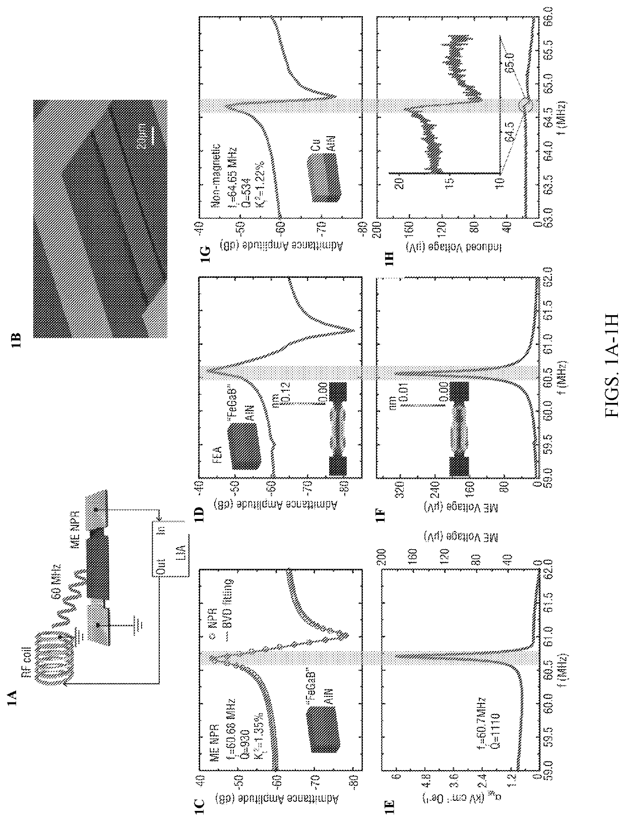
[0120]As shown in FIG. 1C, the admittance amplitude of NPR can be fitted with Butterworth-van Dyke (BVD) model to extract the electromechanical parameters such as electromechanical coupling coefficient kt2and quality factor Q. A BVD equivalent circuit consists of electrical components and equivalent mechanical components connected in parallel. The electrical and the mechanical components constitute the electrical and the mechanical branch, respectively. As shown in FIG. 6, the electrical branch includes device capacitance C0, defined by the device geometry, and resistance R0p associated with dielectric loss. The mechanical branch contains motional capacitance Cm, motional inductance Lm, and motional resistance Rm. These components can be expressed as

Rm=1ω0C0kt2Q,Cm=8π2C0kt2,andLm=1ω02Cm.

Series resistance Rs is connected in serial to both branches as electrical loss of the electrodes. Resonance frequency occurs at 2πω0, where the Cm and Lm cancel eac...

example 4

n of RF Coil

[0121]The RF magnetic field used in the operation of the ME NPR devices described herein is generated by a RF coil with an inner diameter of 7.7 mm and 7 turns. The RF coil was soldered on the SMA port and connected to the out-put port of the lock-in amplifier. The magnetic flux density generated by the RF coil was simulated by Finite Element Method (FEM) software, Comsol Multiphysics V5.1. The input for the simulation was RF voltage with a peak-amplitude of 1V. FIG. 7 shows the magnetic flux density as a function of the center axis coordinate (x). The left end of the coil was placed at x=0 mm and the NPR devices under test was placed at x=14 mm. In this configuration, the magnetic flux density applied to the devices under test was 60 nT.


PUM


Abstract

A nanomechanical magnetoelectric antenna includes a thin film heterostructure that has a magnetic element and a piezoelectric element. The heterostructure is suspended on a substrate and is capable of resonating at acoustic resonance frequencies. In the transmission mode of the antenna, oscillating mechanical strain produced by voltage-induced acoustic waves is transferred to the thin film heterostructure through strain mediated magnetoelectric coupling. This gives rise to magnetization oscillation or magnetic current that radiates electromagnetic waves at the acoustic resonance frequencies. In the receiving mode, the heterostructure senses magnetic components of electromagnetic waves arriving at the antenna, converting these into a piezoelectric voltage output.

Description

CROSS-REFERENCE TO RELATED APPLICATIONS[0001]This application claims the priority of U.S. Provisional Application No. 62 / 343,801, filed May 31, 2017 and entitled “Ultra-Compact RF Magnetoelectric Antennas Based on Acoustic Resonance in NMS Resonators”, which is hereby incorporated by reference in its entirety.BACKGROUND[0002]Antennas that interconvert between electric power and electromagnetic wave radiation act as omnipresent critical components in communication systems including radars, satellites, smart phones, and wireless devices1.2. State of the art compact antennas rely on electromagnetic wave resonance and as such the sizes of these antennas are comparable to the electromagnetic wavelength λ0. Typically, these antennas have a size of more than λ0 / 10, i.e. 1 / 10 of the EM wavelength λ0. This limitation on antenna size has made it challenging to achieve compact electric field sensors and sensor arrays, particularly at very high frequency (VHF; 30˜300 MHz) or ultra-high frequenc...

Claims


Application Information

Patent Timeline
IPC IPC(8): H01L41/08H01L41/18H01Q1/36
CPCH01Q1/364H01L41/18H01L41/08H10N30/00H10N30/85
Inventor SUN, NIAN XIANGLIN, HWAIDERNAN, TIANXIANG
Owner NORTHEASTERN UNIV
Why Eureka
Try Eureka