
Catalytic hydrogel membrane reactor for treatment of aqueous contaminants

Pending Publication Date: 2021-07-29
UNIV OF NOTRE DAME DU LAC
View PDF0 Cites 0 Cited by
  • Summary
  • Abstract
  • Description
  • Claims
  • Application Information

AI Technical Summary

Benefits of technology

The patent text discusses the drawbacks of conventional slurry reactors and fixed bed catalytic reactors used for chemical reactions. The technical effects of the patent are the development of a new approach that combines the benefits of both types of reactors, resulting in improved activity and stability of the catalysts, reduced H2 consumption, and improved mass transfer to the catalyst surface. This new approach alleviates the need for post-treatment filtration and rapid stirring, which are often required with conventional reactors.

Problems solved by technology

While attempts have been made to replace Pd and other platinum group metals (PGMs) with more earth-abundant materials (e.g., metals sulfides and phosphides), their activities are orders of magnitude lower than PGMs, they are unstable in aqueous environments, and / or they require high operating pressures and temperatures.
Although PGMs materials are costly, economic analysis has shown that recent advances in nanotechnology have made PGM catalysts cost competitive compared to other treatment technologies (e.g., ion exchange, air stripping, activated carbon adsorption).
However, full-scale HHC implementation has yet to come to fruition due to mass transfer limitations, costs, catalyst instability, and scalability of current treatment options.
While simple to operate, this approach suffers from disintegration of powdered catalysts due to particle abrasion during mixing, post filtration requirements, inefficient H2 consumption, and / or H2 safety concerns.
For example, the trickle-bed reactor is effective for treating aqueous nitrate, but it has limited reactivity due to H2 solubility limits and poor mass transfer to catalyst surface as well as biofilm fouling during long-term operation.
However, such reactors suffer from complex catalyst synthesis procedures, poor control of catalyst loading, and low contaminant reaction rates.
Further, the scale-up of known reactors are limited by the challenge of immobilizing the catalyst while maintaining efficient mass transport and reaction kinetics.

Method used


Image

  • Catalytic hydrogel membrane reactor for treatment of aqueous contaminants
  • Catalytic hydrogel membrane reactor for treatment of aqueous contaminants
  • Catalytic hydrogel membrane reactor for treatment of aqueous contaminants

Examples


example 1 preparation

of Catalytic Hydrogel Membrane (CHM)

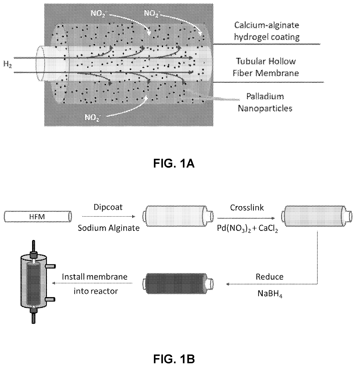
[0096]A representative CHM including a gas-permeable hollow fiber membrane (HFM) coated with an alginate-based hydrogel containing catalyst nanoparticles was prepared using a method involving in-situ reduction of Pd2+ ions enmeshed in the hydrogel (FIG. 1B). Briefly, 2 wt % (weight of alginate / weight of water) alginic acid sodium salt (low viscosity, #01469, Chem-Implex Inc.) was dissolved in ultrapure water (18.2 MΩ-cm) with stirring until homogeneity was achieved. The alginate solution was transferred to a custom-built half-tube reactor for coating. A 25-cm length of the silicone HFM (0.037″ OD×0.025″ ID, #025BRA002, Braintree Scientific, Saint Gobain) was completely submerged in the alginate solution. A 20-mL cross-linking solution (100 mM total concentration) was prepared by dissolving calcium chloride (CaCl2, anhydrous, #C77, Fisher Scientific) and palladium nitrate dihydrate (Pd(NO3)2.2H2O, #76070, Sigma Aldrich) in aqueous solution, which w...

example 2 preparation

of Catalytic Hydrogel Membrane Reactor (CHMR)

[0100]Representative CHMR assembly was constructed by installing CHM of Example 1 in a tubular glass reactor with ports for aqueous and gaseous supplies (FIGS. 3A and 3B). To construct a multifiber CHMR, eight catalytic hydrogel membrane (CHM) strands were inserted in a 25-cm long plastic tube with an inner diameter of 1.27 cm. Plastic T-connectors were installed on both ends of the tubing and the uncoated HFM ends of the CHMs were fixed in place with adhesive (urethane, #2RUD4, Grainger) to create a water-tight seal. Special care was taken to ensure the HFM openings were not crimped or sealed.

example 3

ydrogenation Using CHMR

[0101]The CHM was installed in a tubular glass reactor with ports for aqueous and gaseous supplies, which formed the CHM reactor assembly (FIG. 4A). The aqueous solution was composed of ultrapure water (18.2 MΩ-cm) and 0.35 mM of sodium nitrite (NaNO2, reagent grade, #0535, VWR). For all counter-diffusional experiments, 100% H2 (ultra-high purity, #HY UHPT, American Gas and Welding) was supplied through the lumen of the HFM (operated in closed mode, constant lumen pressure of 3 psi). The majority of experiments were conducted in a recirculating batch system, where the aqueous solution (volume=60 mL) was recycled along the exterior of the CHM using a peristaltic pump. A single experiment using groundwater was conducted using a completely mixed flow reactor consisting of eight CHMs bundled.

[0102]A completely mixed flow reactor was assembled by bundling eight CHMs (7.5% theoretical Pd wt. / dry alginate wt.) in a single reactor vessel (FIG. 4B). The total volume of...


PUM

PropertyMeasurementUnit
Thicknessaaaaaaaaaa
Thicknessaaaaaaaaaa
Pressureaaaaaaaaaa

Abstract

Provided are catalytic assemblies which include a hollow fiber membrane permeable to a gas; a reactive coating permeable to the gas and a contaminant; and a plurality of catalytic nanoparticles embedded in the reactive coating adapted to catalyze a reaction between the gas and the contaminant. Also provided are preparation methods for the catalytic assemblies, and use thereof for treating contaminated water.

Description

CROSS-REFERENCE TO RELATED APPLICATIONS[0001]This application claims the benefit of and priority to U.S. Provisional Application No. 62 / 757,545, filed on Nov. 8, 2018, and U.S. Provisional Application No. 62 / 889,762, filed on Aug. 21, 2019, the entire contents of which are hereby incorporated by reference.STATEMENT OF GOVERNMENT INTEREST[0002]This invention was made with government support under Grant number 1847466 awarded by the National Science Foundation (NSF). The government has certain rights in the invention.INTRODUCTION[0003]Heterogeneous hydrogenation catalysis (HHC) is a reduction process for treating oxidized contaminants using hydrogen gas (H2). For water treatment applications, target reactions occur at the interface between solid (catalyst), liquid (water), and gas phases. Palladium (Pd) is a catalyst for HHC due to high activity and desirable selectivity. While attempts have been made to replace Pd and other platinum group metals (PGMs) with more earth-abundant materi...

Claims


Application Information

Patent Timeline
IPC IPC(8): C02F1/70B01D69/08B01D69/14B01D69/02B01D67/00B01D71/02B01J35/00B01J23/44
CPCC02F1/70B01D69/08B01D69/145B01D69/02B01D67/0088C02F2101/166B01J35/0013B01J23/44B01D2325/04B01D2325/10C02F2305/08B01D71/027C02F2101/163C02F2101/36C02F2101/12B01J35/23
Inventor DOUDRICK, KYLENERENBERG, ROBERTMARKS, RANDAL
Owner UNIV OF NOTRE DAME DU LAC
Learn More