Exhaust gas energy recovery converter

Active Publication Date: 2021-10-07
JTEC ENERGY INC
View PDF0 Cites 0 Cited by
  • Summary
  • Abstract
  • Description
  • Claims
  • Application Information

AI Technical Summary

Benefits of technology

[0011]In one embodiment, the present invention relates to an energy recovery converter for exhaust gases or waste heat. The converter includes a membrane electrode assembly (MEA), an exhaust gas having a first molecular oxygen content, and an external electrical load. The MEA includes a first electrode, a second electrode and an oxygen ion conductive membrane sandwiched between the first and second electrodes. Each of the first and second electrodes includes at least one oxidation catalyst configured to promote an electrochemical reaction. The second electrode of the MEA is exposed to the exhaust gas and the first electrode of the MEA is exposed to a gas having a second molecular oxygen content. The second molecular oxygen content is higher than the first molecular oxygen content. The external electrical load is connected between the first and second electrodes of the MEA.
[0012]In another embodiment, the present invention relates to a method for purifying exhaust gas from a mechanical engine using a converter. The converter includes a catalytic reduction chamber, membrane electrode assembly (MEA), an exhaust gas, and an external electrical load. The MEA includes a first electrode, a second electrode and an oxygen ion conductive membrane sandwiched between the first and second electrodes. Each of the first and second electrodes includes at least one oxidation catalyst configured to promote an electrochemical reaction. The exhaust

Problems solved by technology

The fuel combustion and energy conversion efficiencies of mechanical engines, particularly internal combustion engines, are well understood to be long standing challenges.
It is generally understood that exhaust temperature increases with engine power output, and is directly related to engine inefficiency and the engine's need to dissipate waste heat.
Problems associated with engine inefficiency are essentially two-fold: 1) the percentage of energy available from the fuel that is converted into useful work is limited, and 2) combustion products from the engine include toxic gasses such as NOx, carbon monoxide and partially burned hydrocarbons.
However, catalytic converters also generate waste heat as they catalyze reduction of NOx and complete combustion of remaining fuel products, carbon monoxide (CO) and hydrocarbons (HC) that have not completely burned.
However, prior efforts have yielded limited success, primarily because of cost and/or low efficiency of the available technology.
The complexity associated with coolant loops, which can include heat exchangers, ceramic plates, pumps and

Method used


Image

  • Exhaust gas energy recovery converter
  • Exhaust gas energy recovery converter
  • Exhaust gas energy recovery converter

Examples


Example

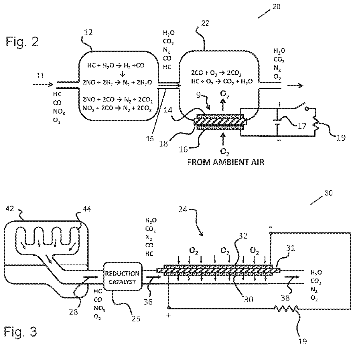
[0022]Referring to FIG. 2, there is shown an energy recovery converter 20 for exhaust gases or waste heat, namely a catalytic converter 20, and more particularly a three-way type catalytic converter 20, according to the present invention. The catalytic converter 20 reduces toxic gases and pollutant in exhaust gas, such as from an internal combustion engine, into less-toxic or harmful exhaust gas. The catalytic converter 20 includes a first chamber 12 and a second chamber 22. The first chamber 12 includes one or more reduction catalysts (and is therefore a catalytic reduction chamber) and the second chamber 22 includes one or more oxidation catalysts (and is therefore a catalytic oxidation chamber). Examples of the reduction catalysts include, but are not limited to, rhodium, platinum, transition metal macrocycles and chalgogenides. In a preferred embodiment, the reduction catalyst of the first chamber 12 is rhodium metal, and more particularly finely divided rhodium metal.

[0023]Engi...


PUM

PropertyMeasurementUnit
Electrical conductoraaaaaaaaaa
Contentaaaaaaaaaa

Abstract

An energy recovery converter for exhaust gases or waste heat is provided. The converter includes a membrane electrode assembly (MEA), an exhaust gas having a first molecular oxygen content, and an external electrical load. The MEA includes a first electrode, a second electrode and an oxygen ion conductive membrane sandwiched between the first and second electrodes. Each of the first and second electrodes includes at least one oxidation catalyst configured to promote an electrochemical reaction. The second electrode of the MEA is exposed to the exhaust gas and the first electrode of the MEA is exposed to a gas having a second molecular oxygen content. The second molecular oxygen content is higher than the first molecular oxygen content. The external electrical load is connected between the first and second electrodes of the MEA.

Description

CROSS-REFERENCE TO RELATED APPLICATIONS[0001]This application claims priority to U.S. Provisional Patent Application No. 62 / 720,996, filed Aug. 22, 2018, the entire disclosure of which is herein incorporated by reference.BACKGROUND OF THE INVENTION[0002]The present invention relates to an energy recovery converter for exhaust gases or waste heat.[0003]The fuel combustion and energy conversion efficiencies of mechanical engines, particularly internal combustion engines, are well understood to be long standing challenges. Piston-type internal combustion engines operate on the Otto cycle, wherein low temperature ambient air is compressed by a piston and then heated to a very high temperature via fuel combustion inside the cylinder of the engine. Expansion of the heated air against the piston as the cycle continues produces more work than is consumed during the initial compression of the air at the low temperature. Other engines, such as combustion turbines and scram jets, are also in t...

Claims


Application Information

Patent Timeline
IPC IPC(8): F01N3/10F01N5/00
CPCF01N3/103F01N5/00F01N2570/14F01N2570/10F01N2570/12F01N3/101B01D53/944B01D53/9454B01D53/9472B01D2255/1021B01D2255/1023B01D2255/1025B01D53/326H01M4/92H01M2008/1293H01M8/002H01M8/2435Y02T10/12Y02E60/50F01N3/108
Inventor JOHNSON, LONNIE G.
Owner JTEC ENERGY INC
Why Eureka
Try Eureka