Method of manufacturing piezoelectric ceramics, piezoelectric ceramics, piezoelectric element, ultrasonic motor, optical apparatus, dust removing device, image pickup apparatus, ultrasonic probe, ultrasonic diagnostic apparatus, and electronic apparatus

a manufacturing method and technology of piezoelectric ceramics, applied in the direction of pictoral communication, mechanical vibration separation, electrical/magnetic means, etc., can solve the problems of large power consumption, small conversion efficiency of electric energy to mechanical energy, and adversely affecting the ecosystem

Pending Publication Date: 2021-10-21
CANON KK
View PDF0 Cites 1 Cited by
  • Summary
  • Abstract
  • Description
  • Claims
  • Application Information

AI Technical Summary

Benefits of technology

[0012]A method of manufacturing a piezoelectric ceramics of the present disclosure for solving the above-mentioned problems is characterized by including: sintering a compact containing a raw material at 1,000° C. or more to obtain a sintered compact; abrading the sintered compact; and annealing the abraded sintered compact to at 800° C. or more and less than 1,000° C.

Problems solved by technology

However, a lead content in a discarded piezoelectric material may elute into soil to adversely affect an ecosystem.
When the electromechanical coupling coefficient is small, the conversion efficiency from electric energy to mechanical energy is small, and the power consumption is increased.
In addition, when the electromechanical coupling coefficient is greatly fluctuated (for example, by more than 35%) depending on the temperature, it becomes difficult to obtain stable element performance within the operating temperature range.
When the mechanical quality factor is small, the electric power required for operation becomes high, or the piezoelectric element generates heat to make drive control difficult.
Thus, although the piezoelectric material exhibits a high piezoelectric constant in the vicinity of room temperature, there is a problem in that the piezoelectric constant and the electromechanical coupling coefficient are significantly fluctuated when the temperature is changed.
In addition, the inventors of the present disclosure have made extensive investigations, and as a result, have found that there is a problem in that the mechanical quality factor at room temperature is as low as less than 500.
Although a high piezoelectric constant and a high electromechanical coupling coefficient are obtained, the surface of the piezoelectric material may undergo grain growth to become rough when the piezoelectric material is subjected to heat treatment at a temperature of 1,000° C. or more.
In the case where the surface becomes rough, when a vibrating body that vibrates together with the piezoelectric material is bonded to the surface thereof with an adhesive, the adhesive enters recesses on the rough surface, with the result that the adhesive becomes thick, and vibration is not easily transmitted from the piezoelectric material to the vibrating body.
As a result, there is a problem in that the drive efficiency deteriorates, and the power consumption is increased.
Also in this case, there is a problem in that the drive efficiency deteriorates, and the power consumption is increased.
In the related art, there is a problem in that the piezoelectric performance of a lead-free piezoelectric material is greatly fluctuated within the operating temperature range of the piezoelectric material, the mechanical quality factor is small, and the surface becomes rough even when an attempt is made to improve the piezoelectric performance by heat treatment at 1,000° C. or more.

Method used

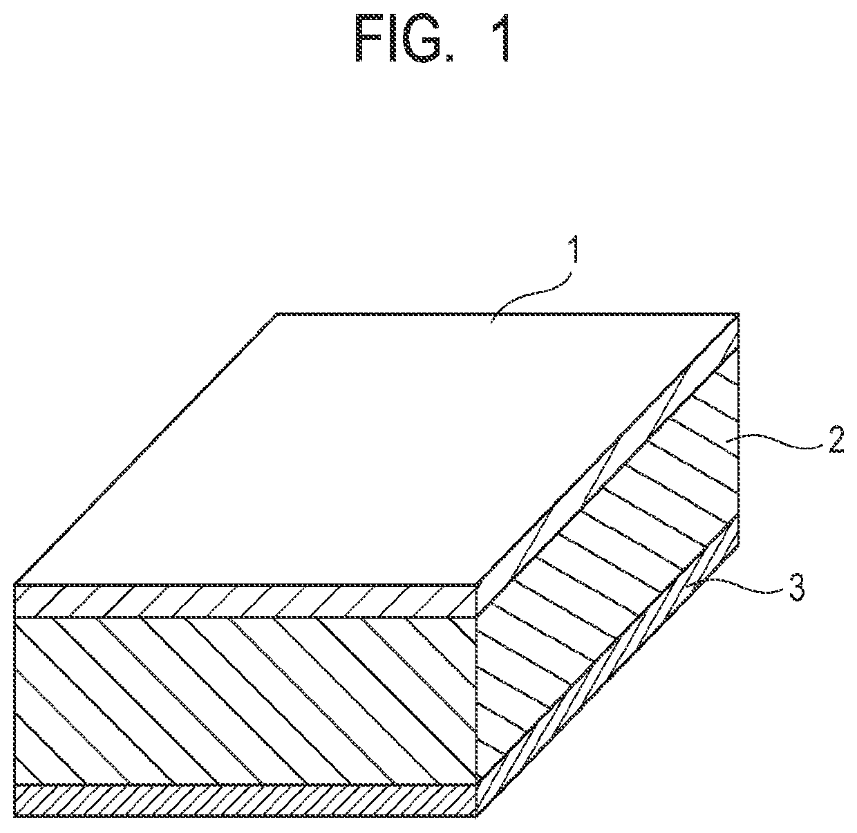
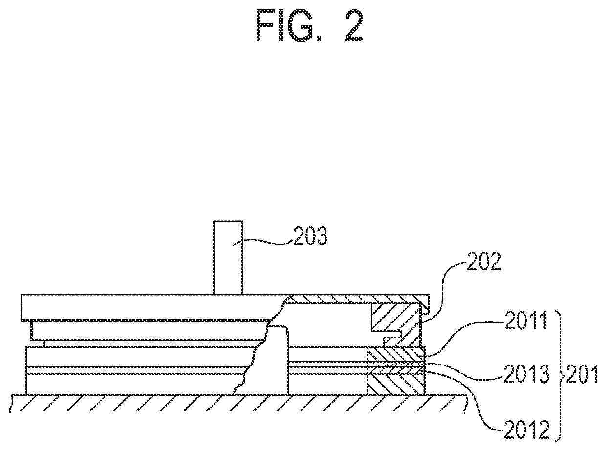
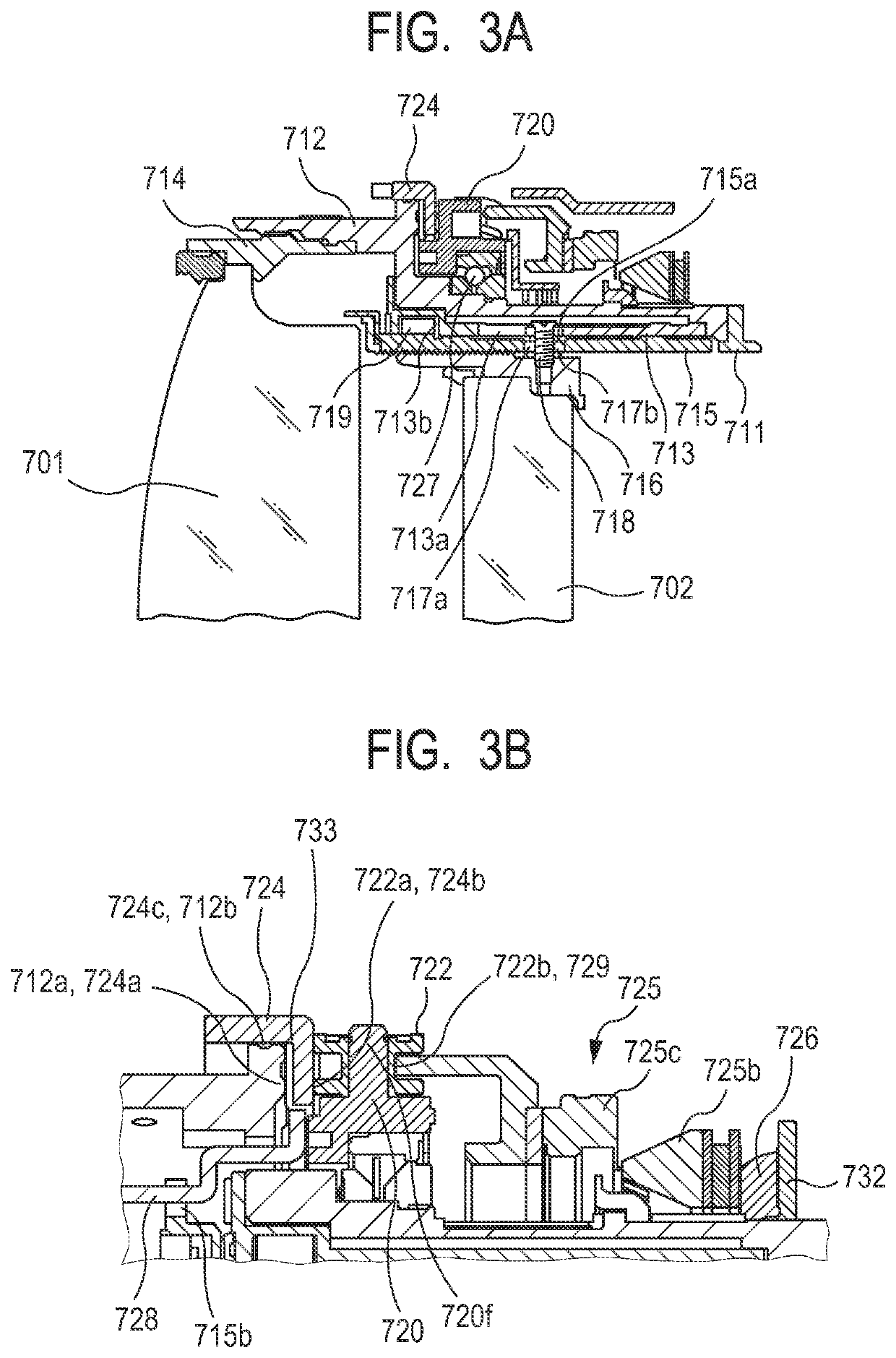

Image

  • Method of manufacturing piezoelectric ceramics, piezoelectric ceramics, piezoelectric element, ultrasonic motor, optical apparatus, dust removing device, image pickup apparatus, ultrasonic probe, ultrasonic diagnostic apparatus, and electronic apparatus
  • Method of manufacturing piezoelectric ceramics, piezoelectric ceramics, piezoelectric element, ultrasonic motor, optical apparatus, dust removing device, image pickup apparatus, ultrasonic probe, ultrasonic diagnostic apparatus, and electronic apparatus
  • Method of manufacturing piezoelectric ceramics, piezoelectric ceramics, piezoelectric element, ultrasonic motor, optical apparatus, dust removing device, image pickup apparatus, ultrasonic probe, ultrasonic diagnostic apparatus, and electronic apparatus

Examples


example 1

[0189]As raw material powders, barium titanate (BaTiO3, Ba / Ti=0.9985) having an average particle diameter of 100 nm, calcium titanate (CaTiO3, Ca / Ti=0.9978), calcium zirconate (CaZrO3, Ca / Zr=0.999), bismuth oxide (Bi2O3), trimanganese tetraoxide (Mn3O4), and barium carbonate for adjusting a ratio “a” of a sum of the numbers of moles of Ti and Zr to a sum of the numbers of moles of Ba and Ca were used. Those raw material powders were weighed so as to obtain a ratio of the composition formula (Ba0.86,Ca0.14)1.002(Ti0.93,Zr0.07)O3 containing titanium and barium as main components. Mn was added to 100 parts by weight of this metal oxide so that the content of Mn became 0.16 part by weight in terms of a metal. Further, Bi was added to the metal oxide having Mn added thereto so that the content of Bi became 0.17 part by weight in terms of a metal, and the resultant was mixed by dry mixing for 24 hours through use of a ball mill. In order to granulate the obtained mixed powder, 3 parts by ...

examples 2 to 8

[0202]Piezoelectric ceramics and piezoelectric elements of Examples 2 to 8 of the present disclosure were obtained through the same steps as those in Example 1 except for the maximum temperature and the retention time of the maximum temperature in the abrading step and the annealing step.

[0203]In the abrading step, both surfaces were abraded through use of an abrasive machine while the size of abrasive grains was changed so that the thickness became 0.5 mm, and finally, finishing abrasion was performed through use of the abrasive machine with abrasive grains of #4,000. Specific numerical numbers of the maximum temperature and the retention time of the maximum temperature in the annealing step are shown in Table 1.

[0204]Subsequently, through the same steps as those in Example 1, the crystal structure of the piezoelectric ceramics forming the piezoelectric element of the present disclosure, the surface roughness Ra before and after the annealing, the electromechanical coupling coeffic...

examples 9 to 11

[0205]Piezoelectric ceramics and piezoelectric elements of Examples 9 to 11 of the present disclosure were obtained through the same steps as those in Example 1 except for the abrading step, the annealing step, and the electrode forming method.

[0206]In the abrading step in each of Examples 9 to 11, both surfaces were abraded through use of an abrasive machine while the size of abrasive grains was changed so that the thickness became 0.5 mm, and finally, finishing abrasion was performed through use of the abrasive machine with abrasive grains of #4,000.

[0207]In addition, in each of Examples 9 to 11, a Ag electrode paste was applied to both surfaces of the piezoelectric ceramics by screen printing instead of a gold electrode paste. The resultant piezoelectric ceramics was placed in an electric furnace, and the annealing step was performed in an air atmosphere, to thereby obtain a piezoelectric element including the piezoelectric ceramics of the present disclosure. The annealing step w...


PUM

PropertyMeasurementUnit
temperatureaaaaaaaaaa
roughnessaaaaaaaaaa

Abstract

Provided are a piezoelectric ceramics which does not contain lead, has small temperature dependence of a piezoelectric constant within an operating temperature range, and has high density, a high mechanical quality factor, a satisfactory piezoelectric constant, and a small surface roughness, and a method of manufacturing the piezoelectric ceramics. The method of manufacturing a piezoelectric ceramics is characterized by including: sintering a compact containing a raw material at 1,000° C. or more to obtain a sintered compact; abrading the sintered compact; and annealing the abraded sintered compact at a temperature of 800° C. or more and less than 1,000° C.

Description

BACKGROUND OF THE INVENTIONField of the Invention[0001]The present disclosure relates to a piezoelectric ceramics and a method of manufacturing the piezoelectric ceramics. The present disclosure also relates to a piezoelectric element, an ultrasonic motor, an optical apparatus, a dust removing device, an image pickup apparatus, an ultrasonic probe, an ultrasonic diagnostic apparatus, and an electronic apparatus which use the piezoelectric ceramics.Description of the Related Art[0002]Lead zirconate titanate containing lead is a typical piezoelectric material, and is used in a variety of piezoelectric devices, such as an actuator, an oscillator, a sensor, and a filter. However, a lead content in a discarded piezoelectric material may elute into soil to adversely affect an ecosystem. Accordingly, in order to exclude lead from piezoelectric devices, research and development on lead-free piezoelectric materials are actively conducted.[0003]When a piezoelectric element is used in a produc...

Claims


Application Information

Patent Timeline
Patent Type & Authority Applications(United States)
IPC IPC(8): H01L41/43B06B1/06H02N2/10H01L41/187G02B7/09B08B7/02C04B35/645C04B35/468A61B8/00H04N5/217G01H11/08
CPCH01L41/43B06B1/0622H02N2/103H01L41/1871G02B7/09B08B7/028G02B7/14C04B35/4682A61B8/4444A61B8/461H04N5/2171G01H11/08B06B2201/76C04B35/645C04B35/49C04B35/64H02N2/12B08B7/02G01N29/245C04B2235/662C04B2235/786C04B2235/963C04B2235/96C04B2235/3263C04B2235/3298C04B2235/3236C04B2235/3208C04B2235/3215H10N30/853H10N30/06H10N30/097B06B2201/71C04B2235/612C04B2235/3244C04B2235/3262C04B2235/5445C04B2235/3248C04B35/6261C04B35/63416C04B2235/604C04B2235/6567C04B2235/77C04B2235/81H02N2/163H02N2/004G02B27/0006H04N23/811H04N23/50H04N23/55H04N23/54H10N30/8536C04B2235/768
Inventor FURUTA, TATSUOMATSUDA, TAKANORIYABUTA, HISATOUEBAYASHI, AKIRA
Owner CANON KK
Why Eureka
Try Eureka