Assessment of skin perfusion using microwave heating and using infrared radiometry
a skin perfusion and infrared technology, applied in the field of infrared thermography and microwave heating, can solve the problems of requiring more complex and costly circuitry to mitigate rfis, limited clinical use of conventional perfusion measurement techniques, and requiring more complicated and costly circuitry
- Summary
- Abstract
- Description
- Claims
- Application Information
AI Technical Summary
Benefits of technology
Problems solved by technology
Method used
Image
Examples
example i
Exemplary Antenna with Hole and Circular Area
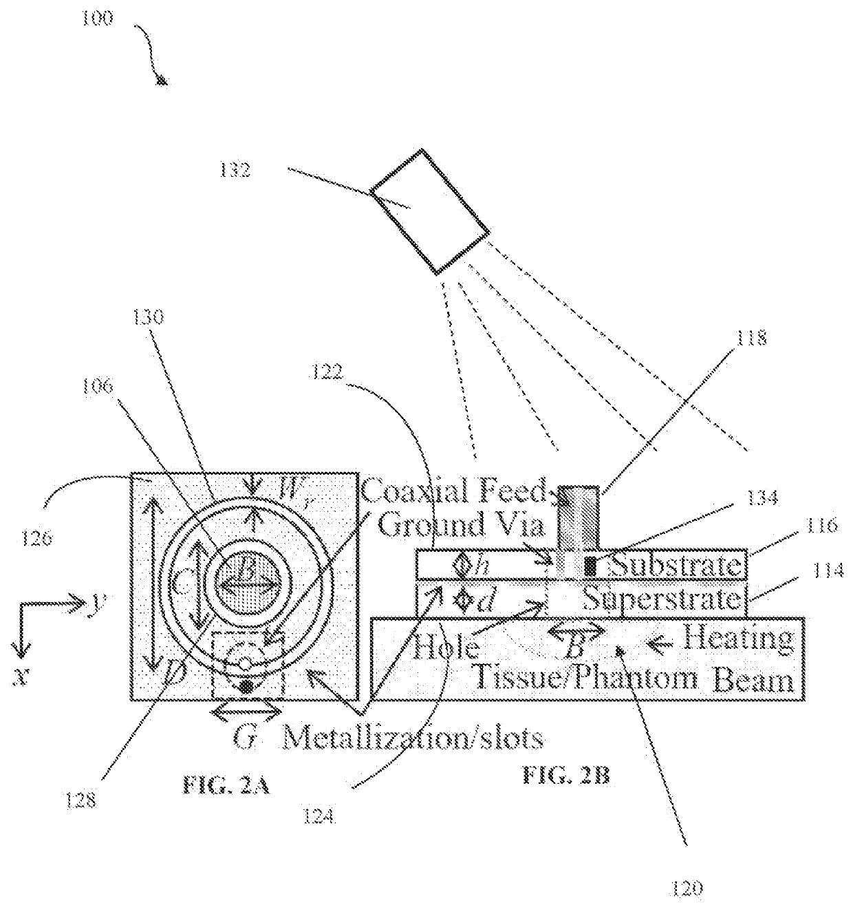
[0085]An embodiment of the antenna 102 configuration of FIGS. 2A-B was constructed and tested. The studies were conducted to test the system 100 for measuring blood perfusion on human skin and small animal skin, and thus the heating was performed at 2.4 GHz, i.e. a shallow heating volume of about 2 cm deep. For purposes of the study, and in reference to FIGS. 2A-B, the diameter of the slot 130 is selected to be D=22 mm, exhibiting a broad S11 resonance around 2 GHz. The substrate material is FR4 with height 1.52 mm and a nominal dielectric constant value of 4.4. The superstrate is a 2.4-mm-thick commercial grade silicone rubber coating (GE Silicone II) with the dielectric constant and loss tangent of 3.12 and 0.01 respectively. A hole 106 with diameter B of about 8 mm is formed into the antenna 102. To secure the coaxial line to the antenna 102, a square shape landing flange of G=10 mm is used. In addition, Wr=1 mm, h=1.52 mm, d=2.4 mm, a...
example ii
Exemplary Antenna Array
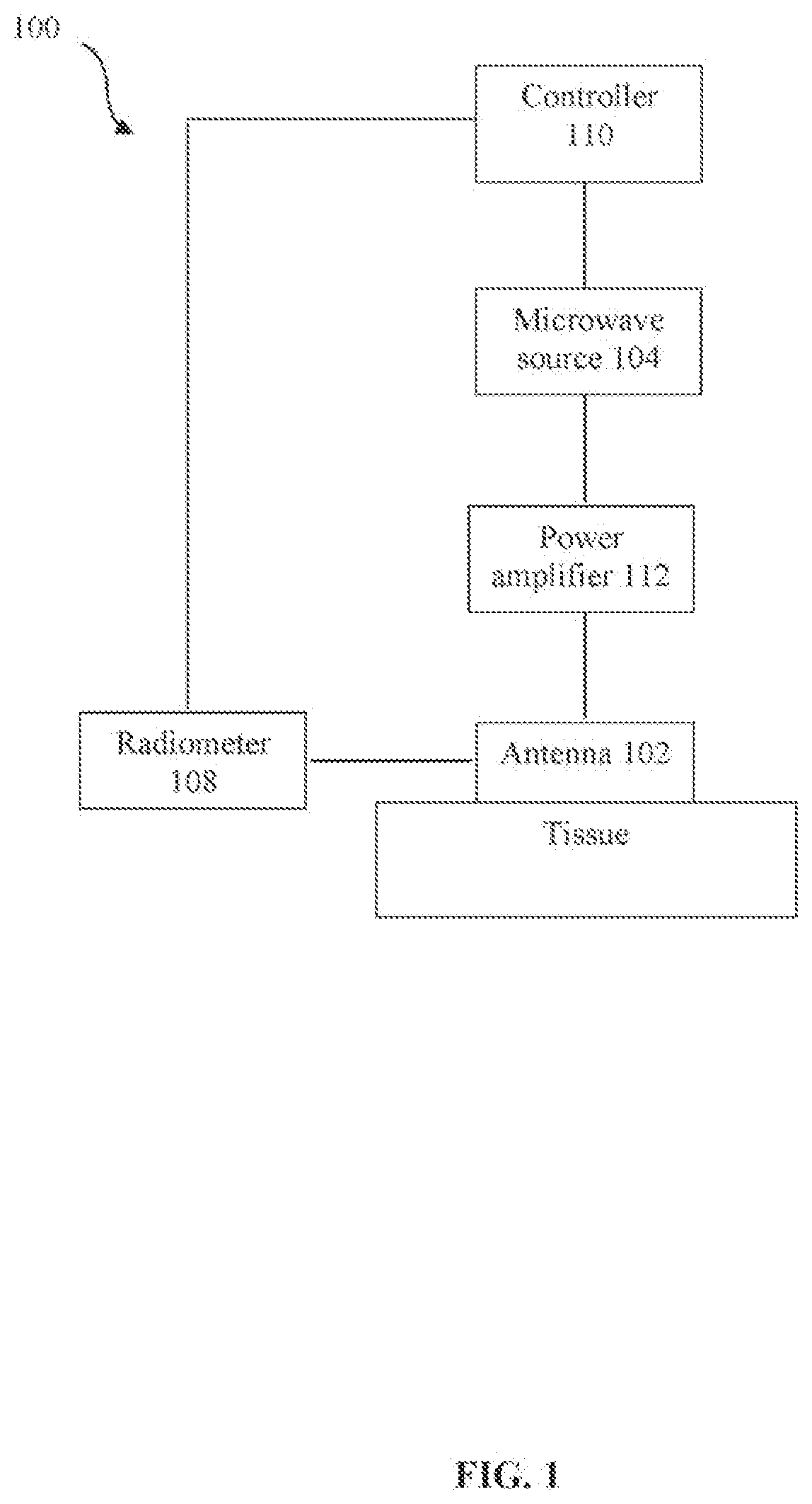
[0090]An embodiment of the antenna array 144 configuration of FIGS. 4-5 and system 100 configuration of FIG. 1 were constructed and tested. The antenna array 144 was constructed and used to perform multi-point measurement of the thermoregulatory response, and thus perfusion. The thermal responses at the holes 106 were simultaneously measured using an infrared camera 132. The recorded temperature for each hole 106 is individually processed by a supporting data processing platform. A 2×1 antenna array (see FIG. 5) operating at 2.45 GHz is designed for the study. The antenna array 144 is a microstrip-fed annular slot antenna with rectangular shape. To make the hole 106 to hole 106 spacing small, a high dielectric constant substrate 116 (Rogers 3010) with ϵr=10.2 and tanδ=0.0035 is used. Annular slots 130 are with rectangular shape, rather than circular, to make a better use of the available space.
[0091]A superstrate 114 overlay coating made of commercial grade si...
example iii
Exemplary Pulse Width Modulation Closed-Loop System
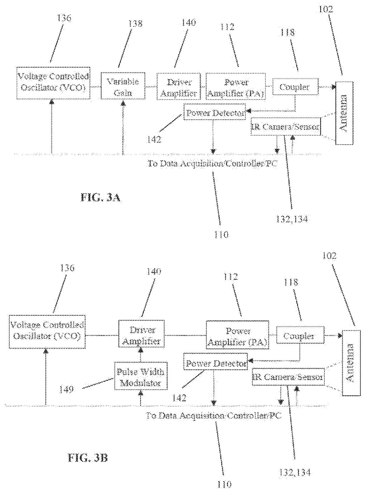
[0099]An embodiment of the antenna configuration of FIGS. 2 and 8 and system 100 configuration of FIGS. 3B, 7, utilizing pulse width modulation control of temperature, was constructed and tested. The antenna 102 was constructed and used to perform single-point measurement of response of variable flow rate and thus perfusion in a perfused phantom (see FIG. 26). The perfused phantom was placed as part of the measurement setup depicted in FIGS. 13B and 27. The perfused phantom is a rectangular block of sponge (140 mm×90 mm×19 mm) is tightly wrapped around by a 4-mil-thick plastic wrap (FIG. 26). The flow is created by a temperature regulated pump / bath (Endocal RTE-8DD, Neslab Instruments, Inc., Portsmouth, N.H.), is controlled by a flowmeter (FL-3803G, OMEGA Engineering, INC., Stamford, Conn.), and then enters and exits the sponge through tubing adapters (inlet and outlet). To seal the phantom, the plastic wrap is sealed at edges by a ...
PUM
| Property | Measurement | Unit |
|---|---|---|
| power | aaaaa | aaaaa |
| microwave radiation power | aaaaa | aaaaa |
| temperature | aaaaa | aaaaa |
Abstract
Description
Claims
Application Information
 - R&D
- Intellectual Property
- Life Sciences
- Materials
- Tech Scout
- Unparalleled Data Quality
- Higher Quality Content
- 60% Fewer Hallucinations
Browse by: Latest US Patents, China's latest patents, Technical Efficacy Thesaurus, Application Domain, Technology Topic, Popular Technical Reports.
© 2025 PatSnap. All rights reserved.Legal|Privacy policy|Modern Slavery Act Transparency Statement|Sitemap|About US| Contact US: help@patsnap.com


