Beam stop apparatus for an ion implanter

Inactive Publication Date: 2000-07-25
APPLIED MATERIALS INC
View PDF25 Cites 13 Cited by
  • Summary
  • Abstract
  • Description
  • Claims
  • Application Information

AI Technical Summary

Problems solved by technology

It has been found that device performance can be compromised if the levels of contamination collect in sensitive re

Method used


Image

  • Beam stop apparatus for an ion implanter
  • Beam stop apparatus for an ion implanter
  • Beam stop apparatus for an ion implanter

Examples


Embodiment Construction

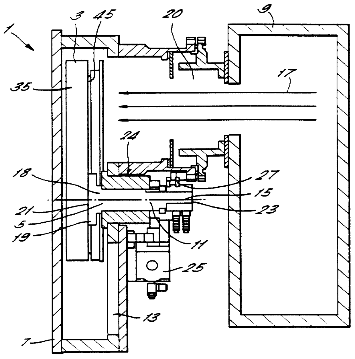
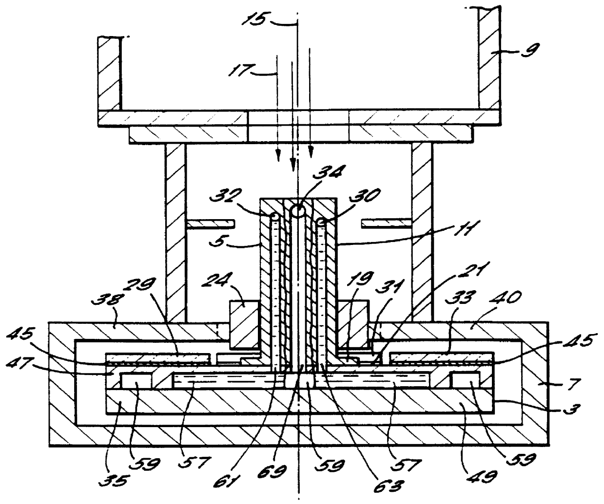
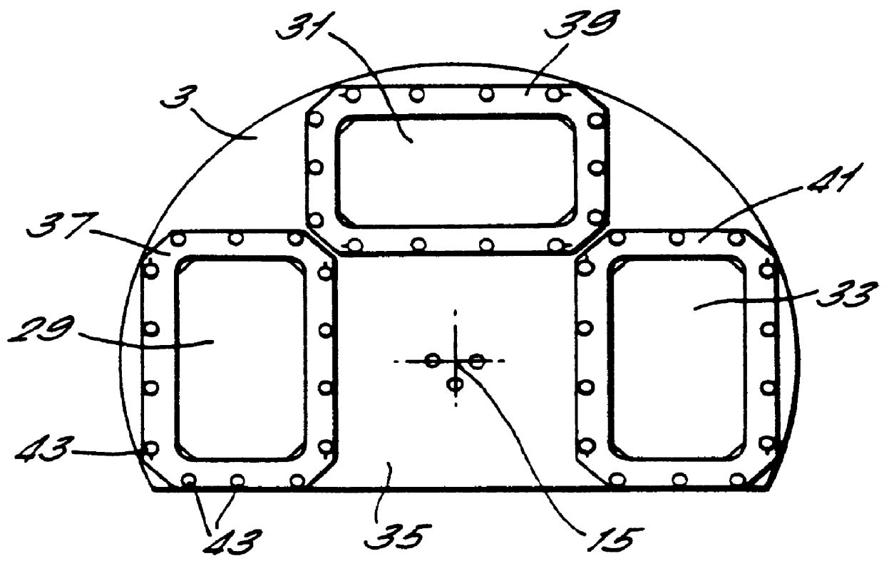
Referring to FIGS. 1 and 2, a beam stop assembly, generally indicated at 1, comprises a beam stop 3 and a rotary support member 5 on which the beam stop 3 is mounted. The beam stop 3 is housed in a vacuum tight enclosure 7 which is mounted on the front end of the beam tube 9 of a conventional ion implanter.

The rotary support member 5 comprises a shaft 11, which extends through the front wall 13 of the enclosure 7 and whose rotational axis 15 is generally parallel to the beam line 17. The end 18 of the shaft 11 which extends into the enclosure 7 is provided with a flange 19 to which the front face 21 of the beam stop 3 is fastened. The other end 23 of the shaft 11 is accessible from outside the enclosure 7 and has a gear wheel (not shown) coaxially mounted thereon which engages with a toothed rack (not shown) driven by a pneumatic actuator 25. A position sensor 27 is positioned near the outer end 23 of the shaft 11 and monitors the angular position of the shaft 11, and hence the posi...


PUM

PropertyMeasurementUnit
Timeaaaaaaaaaa
Timeaaaaaaaaaa
Flow rateaaaaaaaaaa

Abstract

PCT No. PCT/GB95/01309 Sec. 371 Date Dec. 5, 1997 Sec. 102(e) Date Dec. 5, 1997 PCT Filed Jun. 7, 1995 PCT Pub. No. WO96/41364 PCT Pub. Date Dec. 19, 1996An ion beam absorbing apparatus for an ion implanter comprises an ion absorber for absorbing ions in an ion beam generated by the ion implanter, and support means for supporting the ion absorber and adapted for connection with the ion implanter, so that when so connected, the ion absorber can intercept the ion beam and absorb ions not intercepted by a target to be implanted with beam ions. The support means is further adapted for supporting the ion absorber in a plurality of different positions which can be selected so that respective different parts of the ion absorber intercept the ion beam.

Description

This invention relates to ion implanters for implanting ions from an ion beam into semiconductor wafers, and in particular but not limited to ion implanters capable of implanting ions of more than one specie.DESCRIPTION OF THE PRIOR ARTIn ion beam implantation, an ion beam containing dopant ions is generated and directed toward the surface of a semiconductor wafer to dope the wafer in selected regions defined, for example, by a mask. A known ion implanter, as exemplified in U.S. Pat. No. 4,847,504 to Aitken et al, incorporated herein by reference, comprises an ion beam generator for generating a single beam of ions and which can be controlled so that the specie of ions transported by the beam can be selected. A rotatable support is provided for carrying a plurality of semiconductor wafers, comprising a rotatable hub having spokes extending radially therefrom with the end of each spoke adapted to carry an individual wafer. During ion implantation, the support is rotated at high speed...

Claims


Application Information

Patent Timeline
IPC IPC(8): H01J37/317H01J37/30
CPCH01J37/3002H01J37/3171H01J2237/31705
Inventor ENGLAND, JONATHAN GERALDBURGIN, DAVID R.WAUK, MICHAELTODAKA, RYOJI
Owner APPLIED MATERIALS INC
Why Eureka
Try Eureka