Solid surface modification method and apparatus

a technology of solid surface and modification method, applied in the direction of vehicle route interaction device, railway components, nuclear engineering, etc., can solve the problems of unsatisfactory adhesive strength, inability to perform partial modification, and inability to obtain satisfactory adhesive strength, etc., to achieve high interference efficiency, reduce contact area, and high surface treatment efficiency

Inactive Publication Date: 2000-09-12
TOKAI UNIV +1
View PDF36 Cites 49 Cited by
  • Summary
  • Abstract
  • Description
  • Claims
  • Application Information

AI Technical Summary

Benefits of technology

Also, a partial side surface of a window is formed into a plane mirror, and ultraviolet radiation is irradiated obliquely from the side away from the side of the plane mirror such that light directly propagating through the window and light reflected by the internal plane mirror interfere with each other. The result is modification in a diffraction-grating form on the surface of the solid material via the window and a thin layer of a compound liquid film. Especially when the angle of incidence of ultraviolet laser light to be obliquely incident is maintained at a Brewster angle, only p-polarized light brings about interference, resulting in a high interference efficiency. When the surface of a material is modified in the form of a grating, e.g., when a hydrophilic group is substituted in a grating form by using a fluoroplastic material as a solid material to be treated, a hydrophilic or hydrophobic micro domain structure is formed. This allows easy formation of an antithrombotic material necessary for an artificial blood vessel or organ by the use of a fluoroplast

Problems solved by technology

Unfortunately, these conventional chemical modification methods have problems in that, in the case of a fluoroplastic, for example, the surface of a fluoroplastic material turns brown to make the surface layer brittle, resulting in peeling of the adhesive layer.
Consequently, no satisfactory adhesive strength can be obtained.
In addition, although the above conventional methods can modify an entire portion which is immersed, they cannot perform partial modification unless a photoresist is used as a mask.
Also, the treatment reaction is difficult to control, and dangerous chemicals must be used.
However, because of the lack of chemical affinity for an adhesive, a roughened surface formed acts as a stress concentration point, bringing about bonding breakdown.
This makes it impossible to obtain a high bonding strength.
In the

Method used


Image

  • Solid surface modification method and apparatus
  • Solid surface modification method and apparatus
  • Solid surface modification method and apparatus

Examples


example 1

Modification of a fluoroplastic (FEP) sheet was performed by using the apparatus illustrated in FIG. 1. In this example, pure water and tap water were used as the compound solution 2. That is, a thin even liquid film of each of pure water and tap water was formed between the synthetic quartz glass plate 3 and a fluoroplastic (FEP) sheet by pressing the glass plate 3. In this state, an ArF laser beam was irradiated with an energy density of 6.5 mJ / cm.sup.2. Consequently, hydrophilicity was brought about for both pure water and tap water, with the result that a contact angle with water of 30.degree. was obtained.

Note that, for comparison, an identical fluoroplastic (FEP) sheet was dipped in the same solution, and an ultraviolet laser beam was irradiated to perform surface modification for the fluoroplastic (FEP) sheet. As a result, irradiation of an ArF laser beam with an energy density of 6.5 mJ / cm.sup.2 was required to obtain a contact angle with water of 30.degree. when pure water ...

example 2

The apparatus shown in FIG. 1 was used to modify a fluoroplastic (FEP) sheet. In this example, formic acid was used as the compound in solution 2. That is, a thin even liquid film of formic acid was formed between the synthetic quartz glass plate 3 and a fluoroplastic (FEP) sheet by pressing the glass plate 3. In this state, an ArF laser beam was irradiated with an energy density of 25 mJ / cm.sup.2. Consequently, a contact angle with water of 10.degree. was obtained.

Note that, for comparison, an identical fluoroplastic (FEP) sheet was dipped in formic acid, and an ultraviolet laser beam was irradiated to perform surface modification for the fluoroplastic (FEP) sheet. However, modification was impossible because bubbles were generated.

example 3

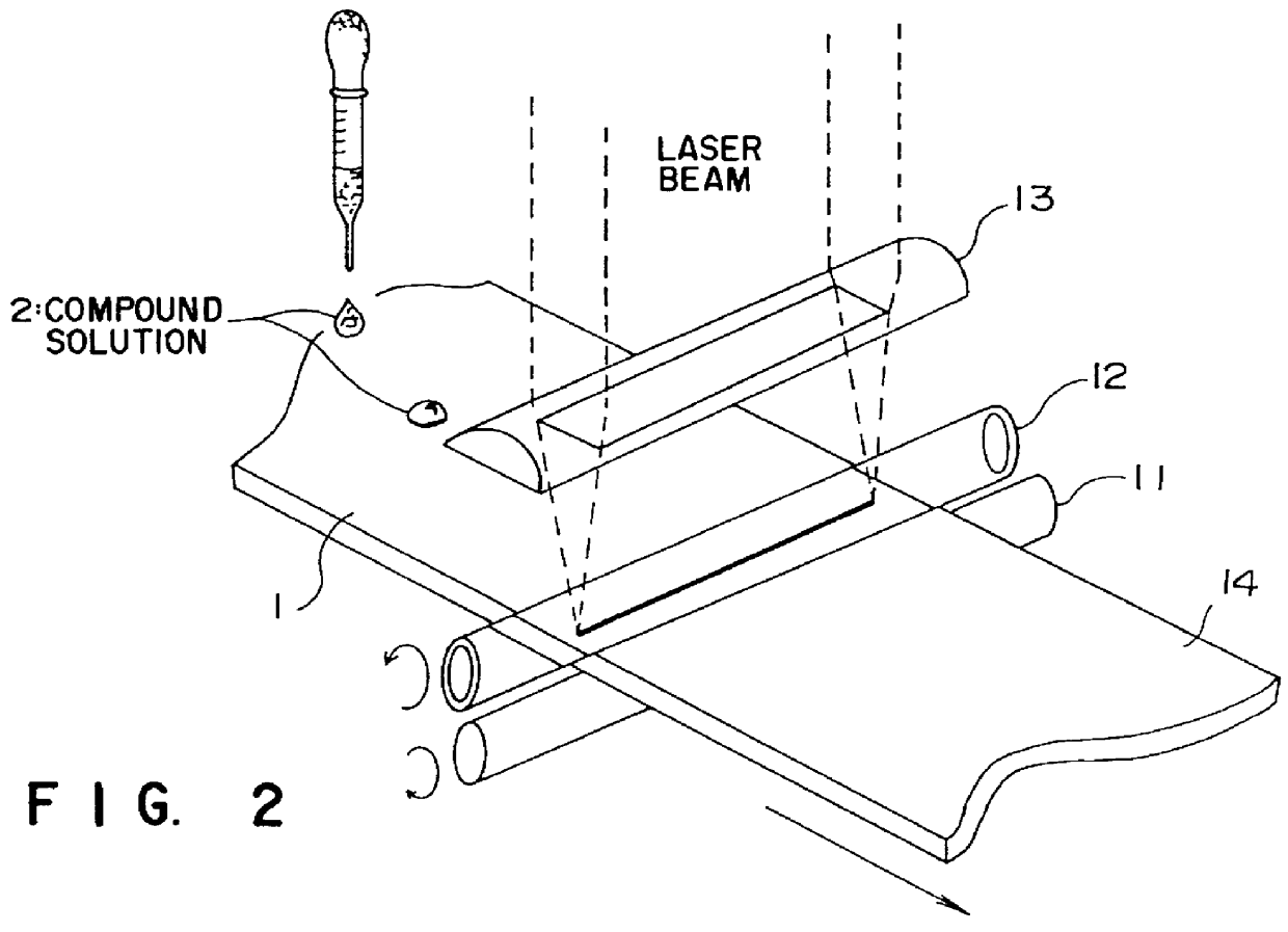
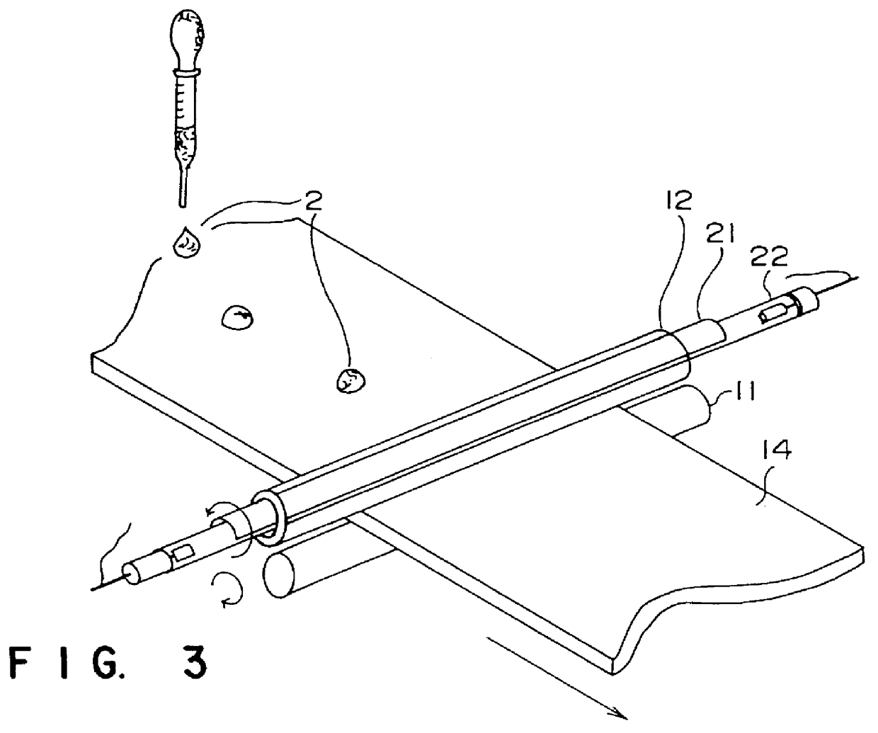
A fluoroplastic (PTFE) sheet was modified by using the apparatuses illustrated in FIGS. 2 and 3. That is, continuous surface modification was done by dropping droplets of methylalcohol (CH.sub.3 OH) one by one on the surface of a fluoroplastic (PTFE) sheet while the fluoroplastic sheet was moved. When an ArF laser beam was irradiated as 3000 shots with an energy density of 25 mJ / cm.sup.2, a contact angle with water of 45.degree. and a contact angle with benzene of 15.degree. were obtained. This demonstrates that the modified surface had both hydrophilic and lipophilic natures.


PUM

PropertyMeasurementUnit
Electrical conductivityaaaaaaaaaa
Adhesivityaaaaaaaaaa
Transparencyaaaaaaaaaa

Abstract

A liquid compound or a compound solution is kept in contact with the surface of a solid material, such as a synthetic resin, glass, metal, or ceramic, radiation selected from ultraviolet radiation, visible radiation, and infrared radiation is irradiated on the interface between the surface of the solid material and the liquid compound or compound solution to optically excite the surface of the solid material and the liquid compound or compound solution, thereby effecting substitution with a chemical species in the liquid compound or compound solution, depositing the chemical species, or performing etching with the chemical species. Preferably, a transparent window is kept in tight contact with the surface of a solid material to be treated, a thin layer of a liquid compound or of a compound solution is interposed between the surface of the solid material and the transparent window by using capillarity, and ultraviolet radiation, visible radiation, or infrared radiation is irradiated through the transparent window. With this treatment, the irradiated portion can be imparted with hydrophilicity, adhesion properties printing properties, a corrosion resistance, and conductivity.

Description

The present invention relates to a method of photochemically modifying the surface of a solid workpiece to be surface-treated, e.g., formed of a synthetic resin, glass, a metal, an animal or a plant, or a ceramic, by bringing a liquid compound in or a compound solution into contact with the surface of the solid workpiece preferably by using a capillary phenomenon, and irradiating the sample with light in this state. The present invention also relates to an adhesion method and a marking method using this surface modification method, and an apparatus for carrying out these methods.There are known a method in which for the purpose of modifying the surface of a fluoroplastic, which is difficult to adhere because of its small affinity for other substances, a fluoroplastic is immersed in a treatment solution comprising liquid ammonia or naphthalene containing metal sodium and tetrahydrofuran to modify the surface, as well as a method of chemically modifying the surface of a polyethylene o...

Claims


Application Information

Patent Timeline
IPC IPC(8): B05D3/06B29C59/00B29C59/16B29D11/00C04B41/00C03C23/00C03C15/00C08J7/12C08J7/00C23F1/00H05K3/38H05K3/18H05K1/03
CPCB05D3/062B29C59/16B29D11/00038B29D11/00461C03C15/00C03C23/0005C04B41/0045C08J7/12C23F1/00C04B41/5353C08J2327/12H05K1/034H05K3/185H05K3/381
Inventor MURAHARA, MASATAKAURAIRI, MASAKATSU
Owner TOKAI UNIV
Why Eureka
Try Eureka