In accordance with the present invention, there are provided magnetic metallic glass alloys that are characterized by relatively linear magnetic responses in the frequency region where harmonic marker systems operate magnetically. Such alloys evidence all the features necessary to meet the requirements of markers for surveillance systems based on
magneto-mechanical actuation. Generally stated the glassy
metal alloys of the present invention have a composition consisting essentially of the formula Fe.sub.a Co.sub.b Ni.sub.c M.sub.d B.sub.e Si.sub.f C.sub.g, where M is selected from
molybdenum,
chromium and
manganese and "a", "b", "c", "d", "e", "f" and "g" are in atom percent, "a" ranges from about 19 to about 29, "b" ranges from about 16 to about 42 and "c" ranges from about 20 to about 40, "d" ranges from about 0 to about 3, "e" ranges from about 10 to about 20, "f" ranges from about 0 to about 9 and "g" ranges from about 0 to about 3. The purity of the above compositions is that found in normal commercial practice. Ribbons of these alloys are annealed with a
magnetic field applied across the width of the ribbons at elevated temperatures below alloys'
crystallization temperatures for a given period of time. The
field strength during the annealing is such that the ribbons saturate magnetically along the field direction. Annealing time depends on the annealing temperature and typically ranges from about a few minutes to a few hours. For commercial production, a continuous reel-to-reel annealing furnace is preferred. In such cases with a furnace of a length of about 2 m, ribbon travelling speeds may be set at about between 0.5 and about 12 meter per minute. The annealed ribbons having, for example, a length of about 38 mm, exhibit substantially linear
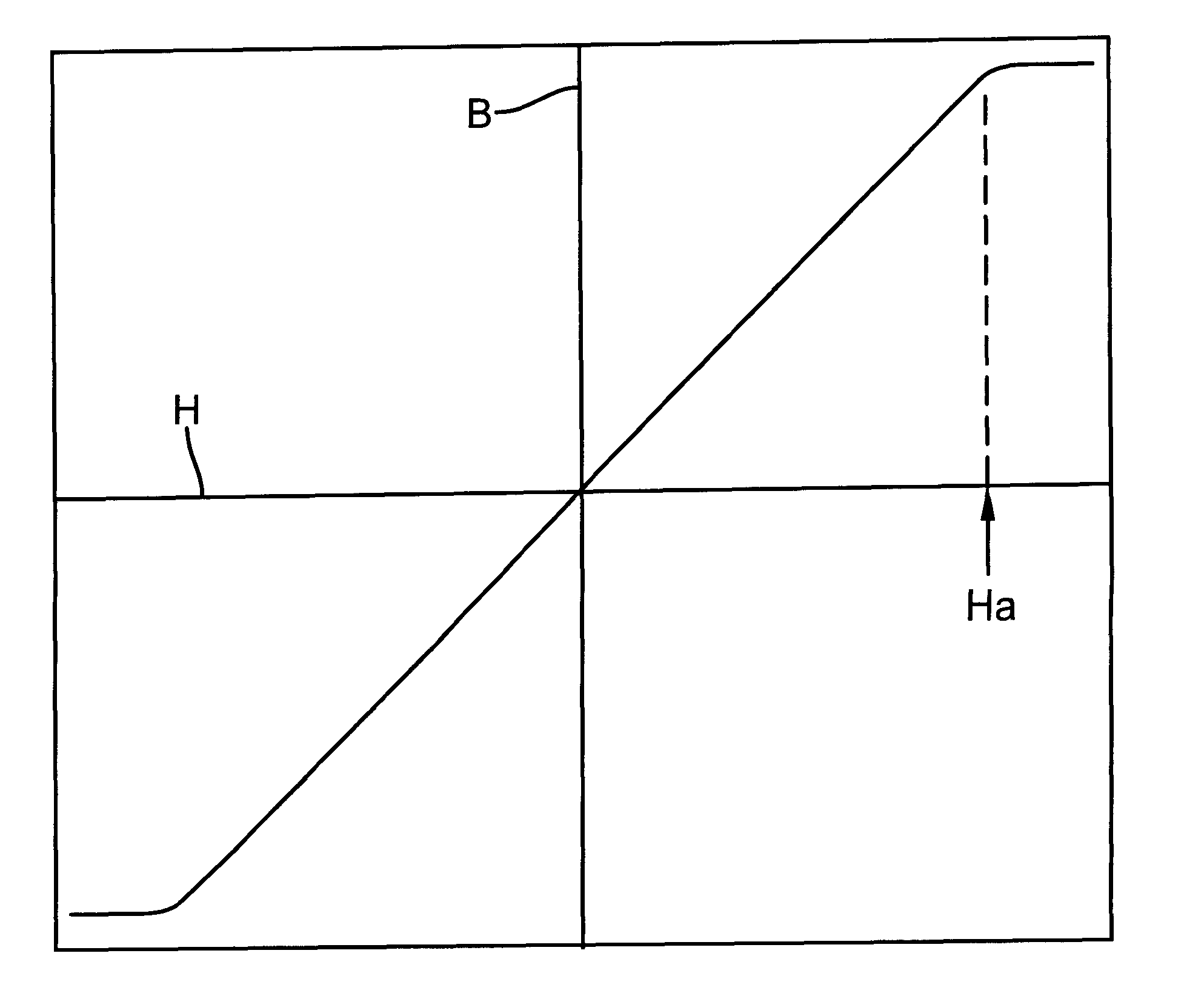
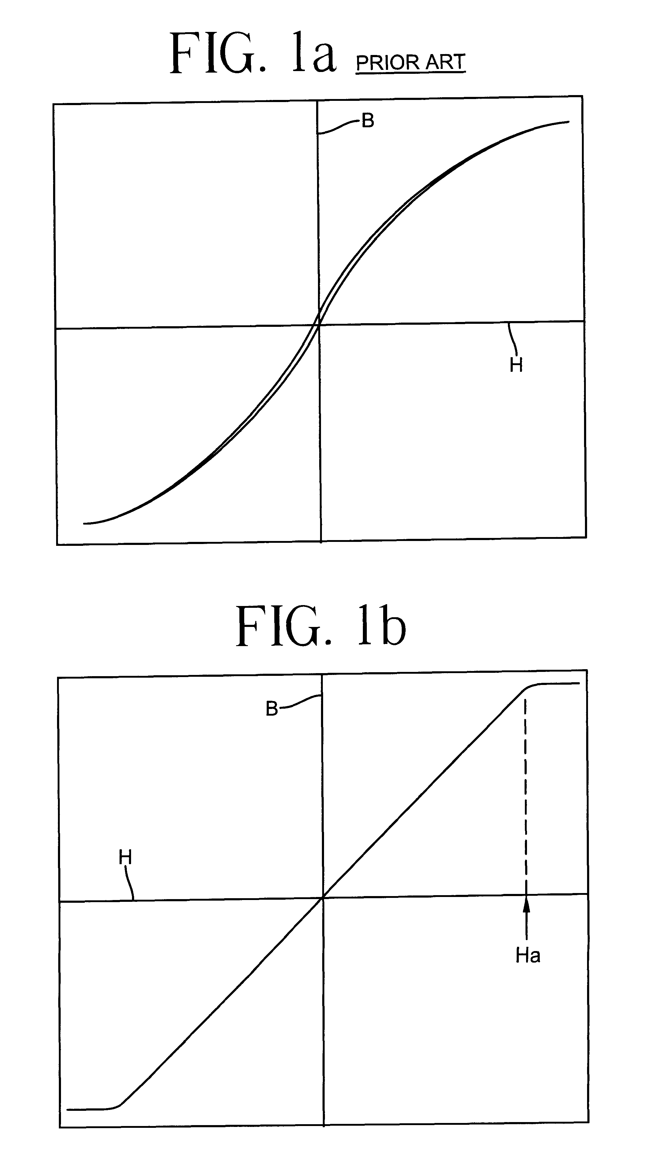
magnetic response for magnetic fields of up to 8 Oe or more applied parallel to the marker length direction and
mechanical resonance in a range of frequencies from about 48 kHz to about 66 kHz. The linear
magnetic response region extending to the level of 8 Oe is sufficient to avoid triggering some of the harmonic marker systems. For more stringent cases, the linear magnetic response region is extended beyond 8 Oe by changing the
chemical composition of the
alloy of the present invention. The annealed ribbons at lengths shorter or longer than 38 mm evidence higher or lower mechanical
resonance frequencies than 48-66 kHz range. The annealed ribbons are ductile so that
post annealing cutting and handling cause no problems in fabricating markers.
Apart from the avoidance of the interference among different systems, the markers made from the alloys of the present invention generate larger signal amplitudes at the receiving coil than conventional mechanical resonant markers. This makes it possible to reduce either the size of the marker or increase the detection
aisle widths, both of which are desirable features of article surveillance systems.
Magnetostrictive effects are observed in a ferromagnetic material only when the
magnetization of the material proceeds through
magnetization rotation. No
magnetostriction is observed when the magnetization process is through
magnetic domain wall motion. Since the
magnetic anisotropy of the marker of the alloy of the present invention is induced by field-annealing to be across the marker width direction, a dc
magnetic field, referred to as
bias field, applied along the marker length direction improves the efficiency of
magneto-mechanical response from the marker material. It is also well understood in the art that a
bias field serves to change the effective value for E, the Young's modulus, in a ferromagnetic material so that the mechanical
resonance frequency of the material may be modified by a suitable choice of the
bias field strength. The
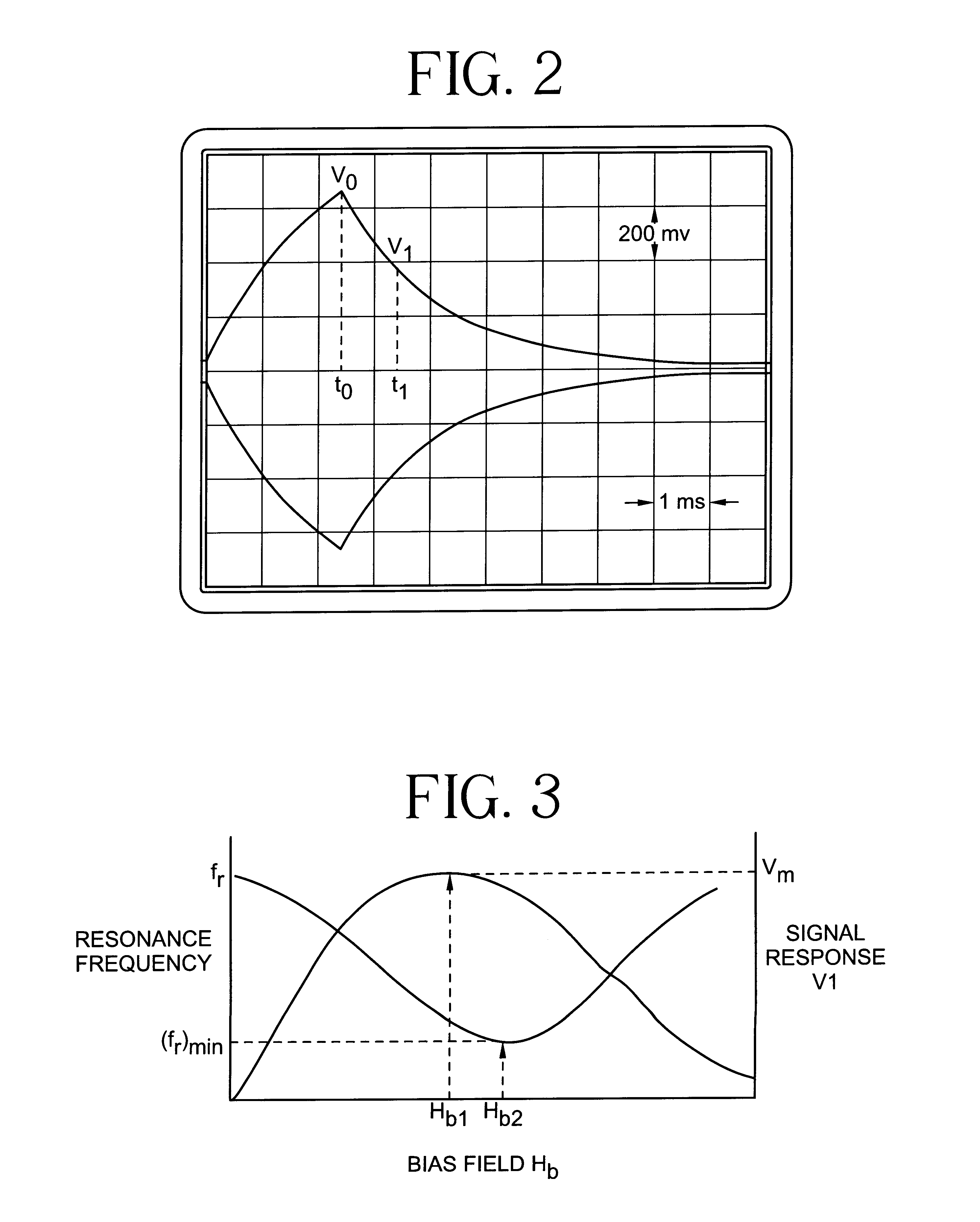
schematic representation of FIG. 3 explains the situation further: The
resonance frequency, f.sub.r, decreases with the bias field, H.sub.b, reaching a minimum, (f.sub.r).sub.min, at H.sub.b2. The quantity H.sub.b2 is related to the
magnetic anisotropy of the marker and thus directly related to the quantity H.sub.a defined in FIG. 1b. The
signal response, V.sub.1, detected, say at t=t.sub.1 at the receiving coil, increases with H.sub.b, reaching a maximum, V.sub.m, at H.sub.b1. The slope, d.sub.f / dH.sub.b, near the operating bias field is an important quantity, since it related to the sensitivity of the surveillance system.

