

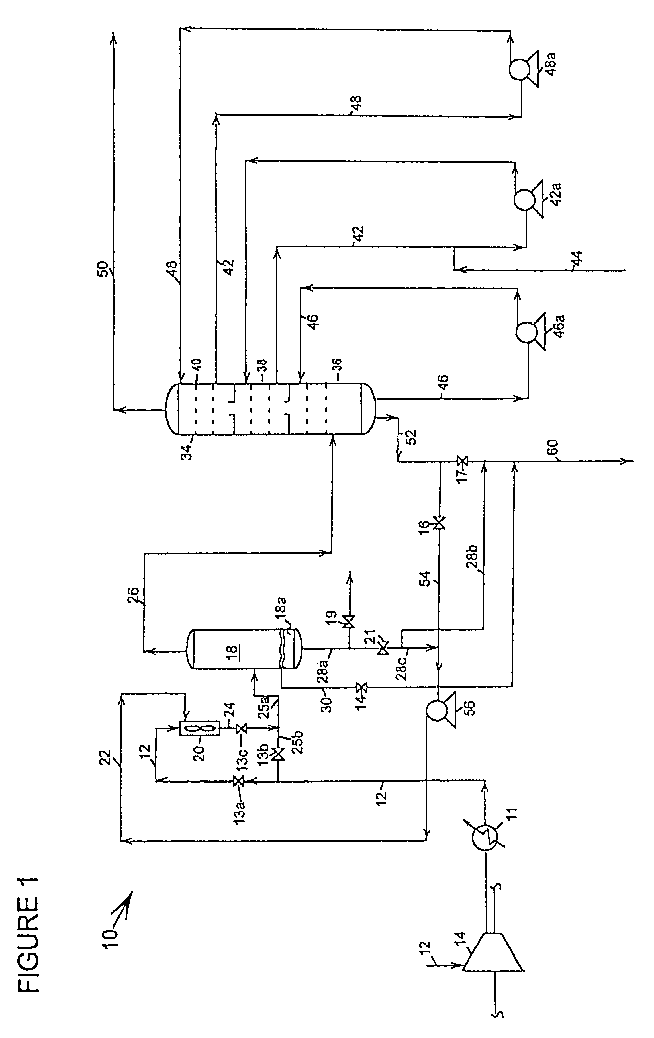
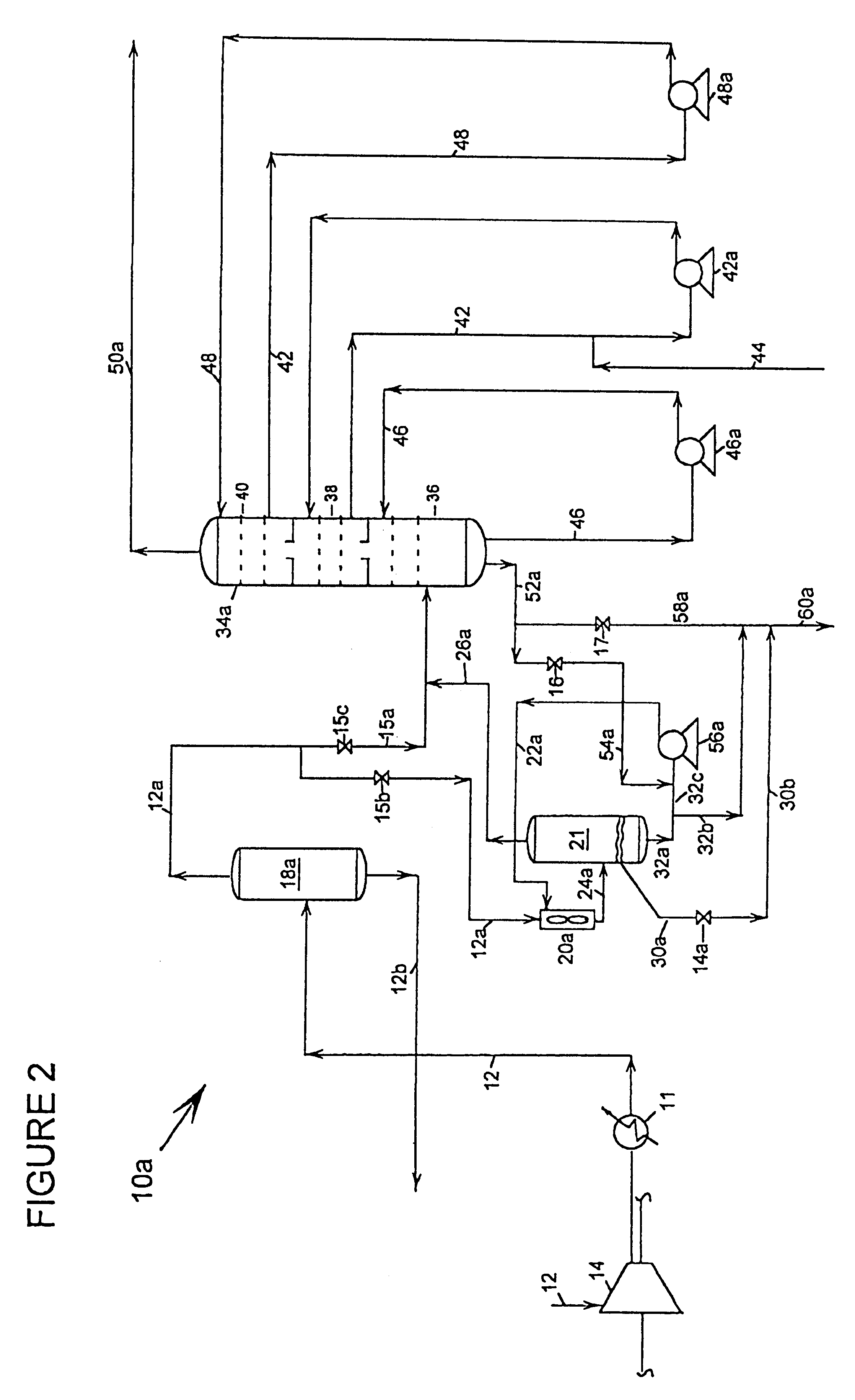
Process for pretreating cracked gas before caustic tower treatment in ehtylene plants
a technology of ehtylene plant and crack gas, which is applied in the direction of hydrogen sulfide, gaseous mixture working up, separation process, etc., can solve the problems of reducing equipment efficiency and capacity, establishing equipment limits for ethylene production, and affecting the etc., to achieve the effect of reducing polymer material deposits, increasing efficiency and capacity of caustic towers, and improving throughput rates
- Summary
- Abstract
- Description
- Claims
- Application Information
AI Technical Summary
Benefits of technology
Problems solved by technology
Method used
Image

Examples
example
Simulation runs using computer modeling provide an estimate of the benefits and advantages of incorporating a high-shear contractor for mixing a weak or weakened caustic with the cracked gas stream upstream of the caustic tower. Table 1 provides a base case of typical operating data for cracked gas feed to a caustic tower, fresh caustic input to the caustic tower, treated gas from the caustic tower, and spent caustic from the caustic tower for a typical ethylene plant operated at a 90% utilization of fresh caustic input prior to installation of a high-shear contractor.
From Table 1, illustrating a conventional operation of a caustic tower, polymer precursors in the untreated gas is at 400 vppm and the treated gas has 100 vppm. This means 300 vppm (.apprxeq.515 lb / hr) of precursors reacted to form polymers in the caustic tower.
For comparison to the base case, Table 2 provides operating data for the same ethylene plant, but with a high-shear inline static mixer installed upstream of th...
PUM
| Property | Measurement | Unit |
|---|---|---|
| Fraction | aaaaa | aaaaa |
| Fraction | aaaaa | aaaaa |
| Fraction | aaaaa | aaaaa |
Abstract
Description
Claims
Application Information