Process and system for operating magnetron discharges

Inactive Publication Date: 2002-01-22
FRAUNHOFER GESELLSCHAFT ZUR FOERDERUNG DER ANGEWANDTEN FORSCHUNG EV
View PDF31 Cites 51 Cited by
  • Summary
  • Abstract
  • Description
  • Claims
  • Application Information

AI Technical Summary

Problems solved by technology

Because of numerous disadvantages, however, this process has only been used on a limited technical scale.
With the reactive deposition of electrically insulating layers using direct current sputtering of metallic targets in a gas mixture which, in addition to inert gas, also contains amounts of reactive gasses such as oxygen or nitrogen, two fundamental difficulties arise.
One difficulty is the lack of long-term stability of the discharge.
This leads to a lack of constancy in the process parameters so that the discharge finally can no longer be ignited or so that the technical parameter limits of the power supply device no longer suffice.
The second difficulty is the occurrence of arc discharges, which are called "Arcing" and which sometimes also occur when operating nonreactive magnetron discharges.
As a result of these charges, electrical short circuits in the form of above-mentioned arc discharges occur, which cause defects in the layers and on the target surface and inhibit a sufficient process stability.
As a result, the long-term stability of the magnetron discharges is improved and the usable processing time is extended, but the problem remains fundamentally unsolved.
However, highly insula

Method used


Image

  • Process and system for operating magnetron discharges
  • Process and system for operating magnetron discharges
  • Process and system for operating magnetron discharges

Examples


Example

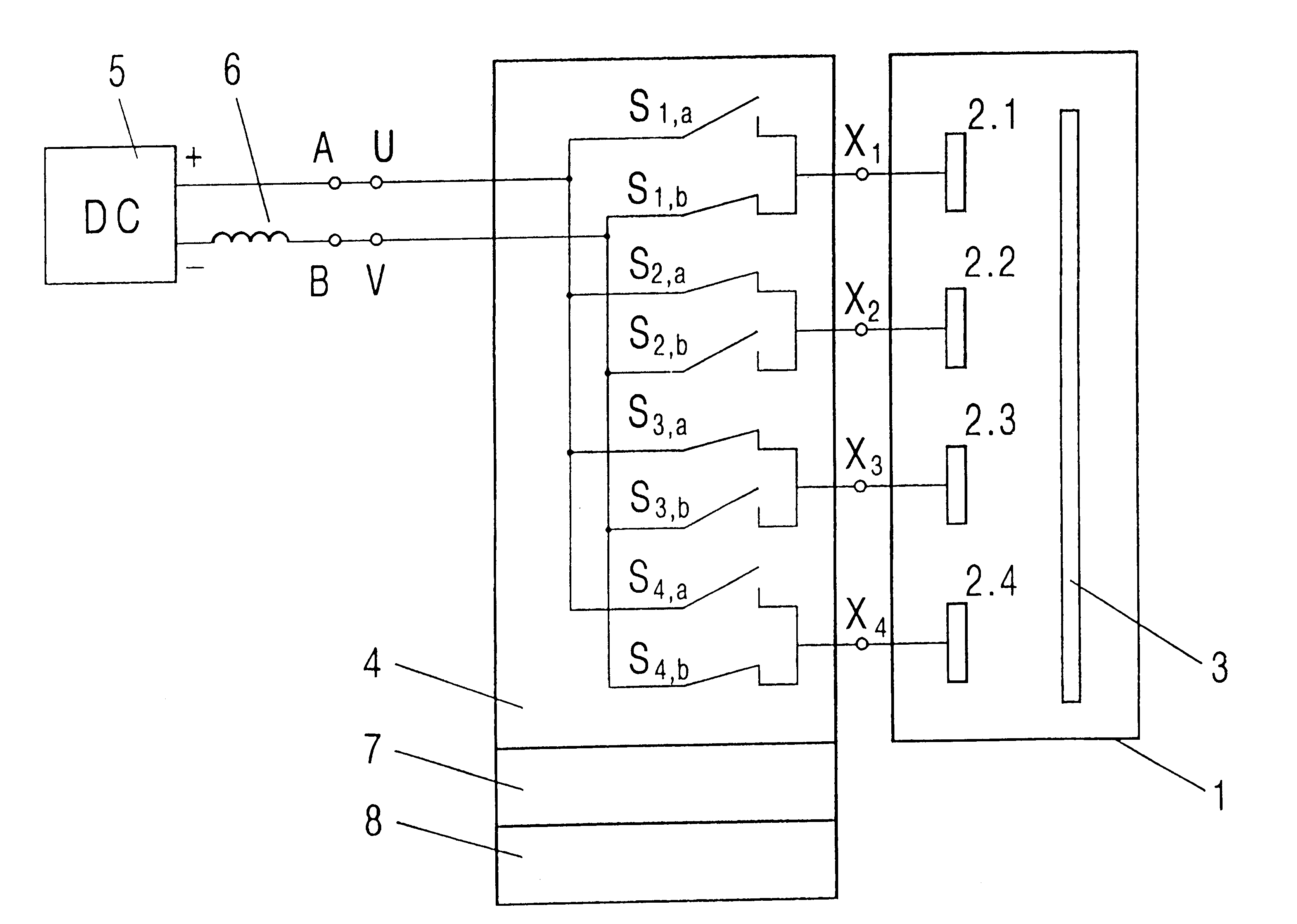
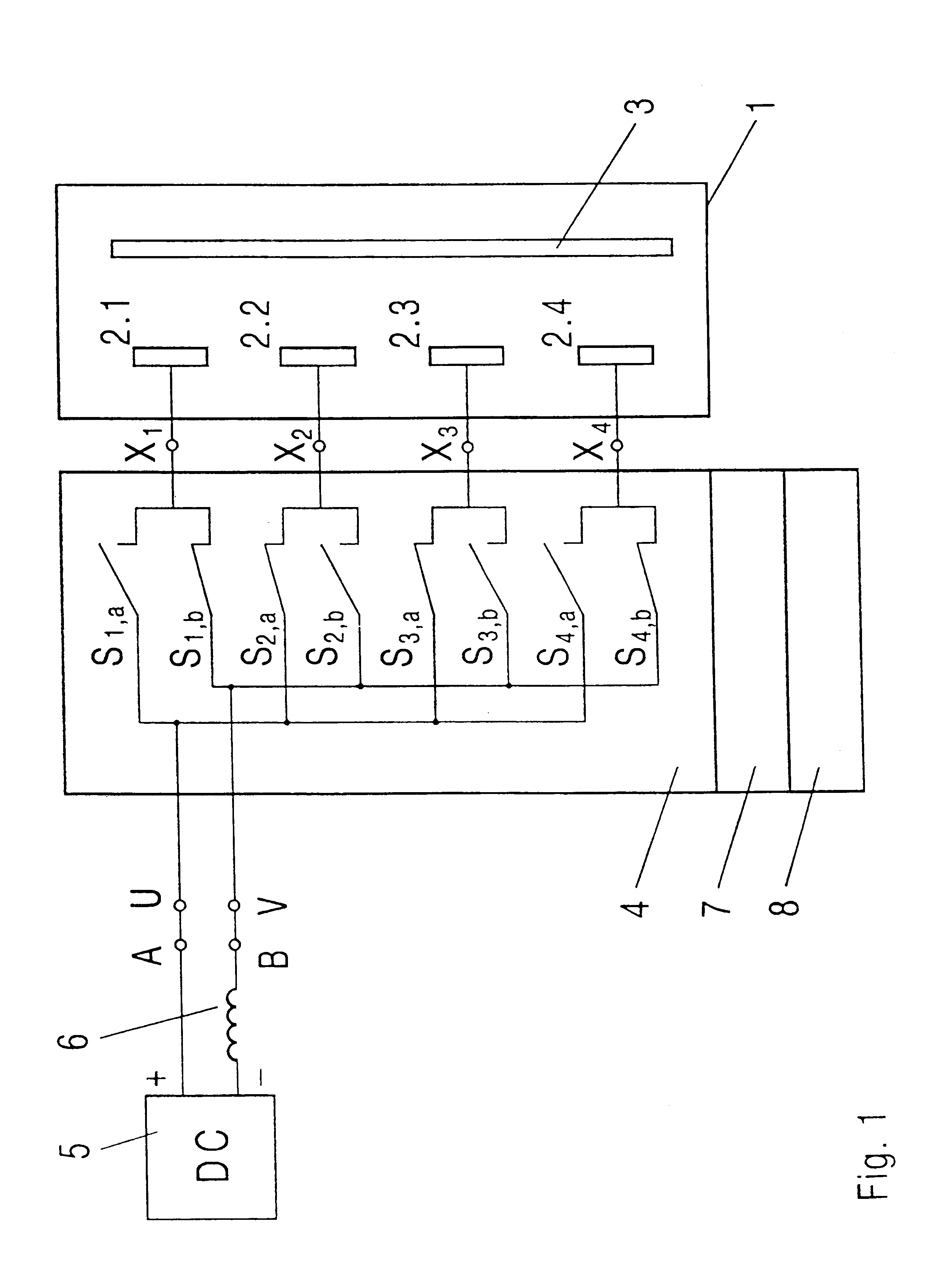
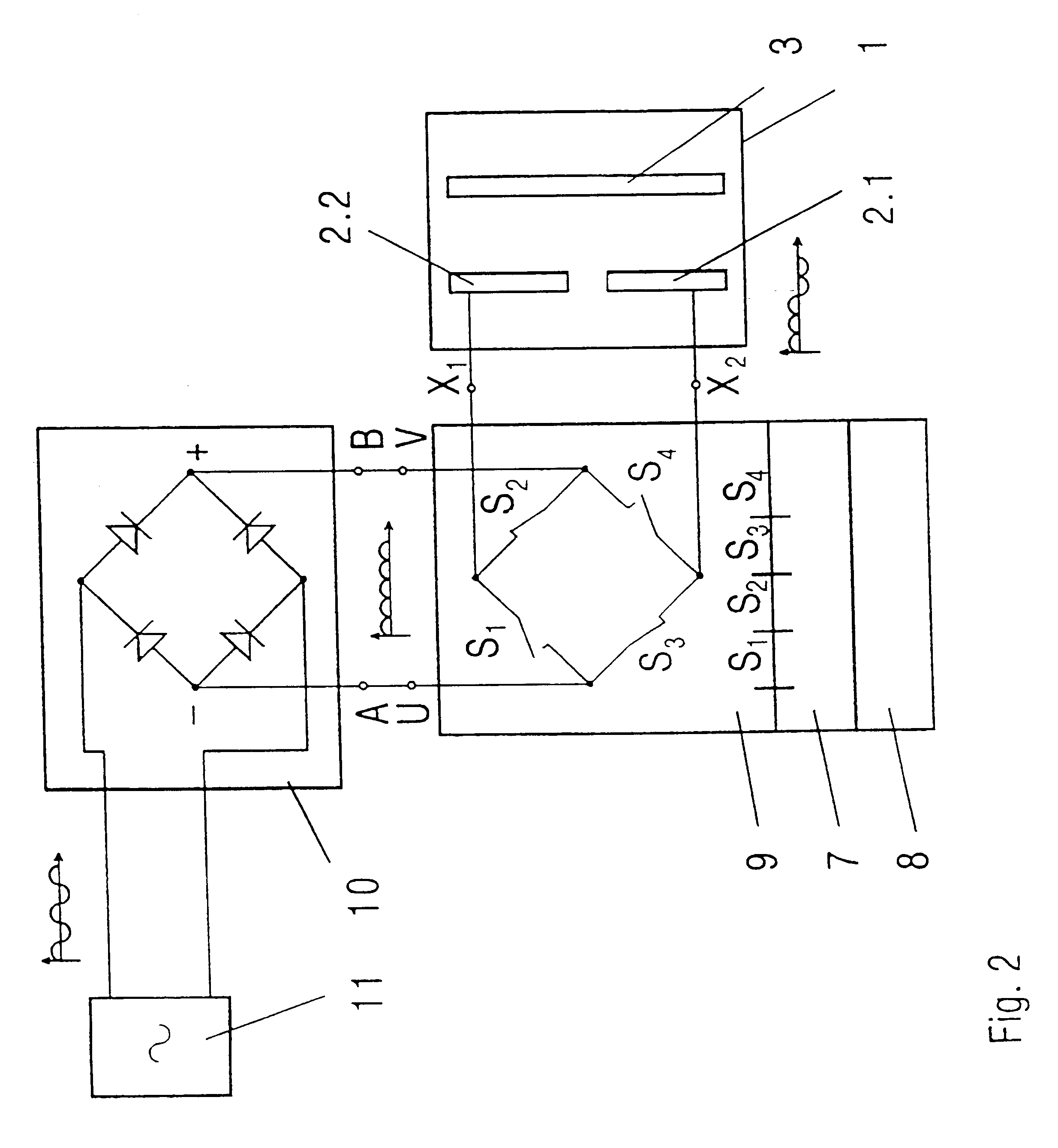
In FIG. 1, four magnetron electrods 2.1-2.4 and a substrate 3 to be coated are disposed in a vacuum chamber 1. The magnetron electrodes 2.1-2.4 contain the material to be sputtered in the form of targets, which have been respectively penetrated by the magnetic field of the corresponding magnetron electrode 2.1-2.4. The magnetron electrodes 2.1-2.4 are connected by way of outputs X.sub.1 -X.sub.4 with a controlled electronic switch unit 4. Each output X.sub.1 -X.sub.4 is respectively connected to two switches S.sub.a and S.sub.b. The controlled electronic switch unit 4 is connected by way of the inputs U and V and with the poles A and B of a direct current generator 5, wherein the direct current generator 5 comprises an inductor 6 at the pole B. The control of the electronic switch unit 4 is carried out by the control unit 7. A detector circuit 8 for arc discharges is integrated into the device.

Through direct current generator 5, the inductor 6, and the controlled electronic switch u...


PUM

PropertyMeasurementUnit
Frequencyaaaaaaaaaa
Frequencyaaaaaaaaaa
Frequencyaaaaaaaaaa

Abstract

Magnetron discharges are pulse-operated to avoid the so-called "arcing". In the case of magnetron discharges from alternating current-fed magnetrons, the process is limited to the minor power of the energy supply because of the load-carrying capacity of the required electric components. When the magnetron discharges are fed by direct current, their effectiveness deteriorates because of the deposition of layers on the anode surfaces. The new process should enable a high supply power and prevent arcing. In magnetron discharges with at least two magnetron electrodes, the energy is supplied in such a way that at least one magnetron electrode is a cathode or anode and a number n1 of direct current pulses of said polarity is supplied. The poles of at least one magnetron electrode are then reversed and a number n2 of direct currents of this polarity are supplied. The process is carried on in this manner, the frequency of the direct current pulses being higher than that of the polarity reversals. The energy supply effectiveness is thus improved. This process and system enable the production of layers having the most different properties, for example for the glass, packaging, electronic, and machine construction industries.

Description

1. Field of the InventionThe invention relates to a process and an associated system for operating magnetron discharges. Magnetron discharges are used widely in vacuum coating technology. The most important field of application is magnetron atomization, also called sputtering, for depositing thin layers of metals, alloys, or reactively deposited chemical compounds, such as oxides or nitrides. Furthermore, magnetron discharges are used to generate the plasma in plasma-activated reactive vaporization. Another field of application is the generation of magnetron enhanced plasmas for the pretreatment of substrates before the vacuum coating. Important fields of application are the manufacture of optically effective layers in the glass industry, the manufacture of decorative, wear-reducing and hard layers in the tool industry and the machine construction industry, the manufacture of barrier layers in the packaging industry, and the manufacture of insulating layers for electronics and for d...

Claims


Application Information

Patent Timeline
IPC IPC(8): H01J37/32H01J37/34
CPCH01J37/34
Inventor GOEDICKE, KLAUSWINKLER, TORSTENJUNGHAHNEL, MICHAELFIETZKE, FREDKIRCHHOFF, VOLKERRESCHKE, JONATHAN
Owner FRAUNHOFER GESELLSCHAFT ZUR FOERDERUNG DER ANGEWANDTEN FORSCHUNG EV
Why Eureka
Try Eureka