Electrical impedance tomography to control electroporation

a technology electroporation, which is applied in the field of electric impedance tomography to control electroporation, can solve the problems of inability to adapt the procedure as currently practiced to the specific characteristics of individual cells, inability to achieve the effect of avoiding cell damage, avoiding the cellular specificity of such vectors, and precise amount of electroporation

Inactive Publication Date: 2002-05-14
RGT UNIV OF CALIFORNIA
View PDF4 Cites 223 Cited by
  • Summary
  • Abstract
  • Description
  • Claims
  • Application Information

AI Technical Summary

Benefits of technology

An advantage of the invention is that a precise amount of electroporation can be obtained and cell damage avoided by controlling any given electrical parameter (e.g. current and / or voltage) applied based on real time measurements of changes in current which relates to the amount of electroporation being obtained.
is that a precise amount of electroporation can be obtained and cell damage avoided by controlling any given electrical parameter (e.g. current and / or voltage) applied based on real time measurements of changes in current which relates to the amount of electroporation being obtained.
Another advantage of the invention is that it can be used to transfect cells with nucleotide sequences without the need for packaging the sequences in a viral vector for delivery, thereby avoiding the cellular specificities of such vectors.
Still other advantages are that the process can be carried out relatively quickly with a relatively low degree of technical expertise.
Yet another advantage is that the process can be used to transfect cells without generating an immune response.
Still another advantage is that the process is not limited by the size of the DNA (i.e. the length of the DNA sequences) and the amount of DNA brought into a cell can be controlled.

Problems solved by technology

Unfortunately, the degree of permealization occurring in electroporation varies with the cell type and also varies among cells in a given population.
Furthermore, since the procedure is performed in large populations of cells whose properties vary among the individual cells in the population, the electroporation conditions can only be selected to address the average qualities of the cell population; the procedure as currently practiced cannot be adapted to the specific characteristics of individual cells.
Of particular concern is that under certain conditions, the electrical potential is too low for a cell membrane to become permeabilized, while under other conditions electroporation can induce irreversible pore formation and cell death.
A further problem with known methods of electroporation is that the efficiency of transfection by electroporation can at times be low.
Many of the problems identified above are a consequence of the fact that the process of electroporation in both individual cells and tissues cannot be controlled in real time.
There are no means at present to ascertain in real time when a cell enters a state of electroporation.
As a result, the outcome of an electroporation protocol can only be determined through the eventual consequences of the mass transfer process and its effect on the cell.
This bulk transfer method does not permit precise control or measurement of the mass transfer across the membrane.
Furthermore, the surface of the cell that is exposed to the solution is not well defined.
Cell surface areas vary among cells in a given population, and this leads to significant differences among the cells in the amount of mass transfer.
For these reasons, the amount of mass transfer achieved by bulk transfer processes is not uniform among cells, and the actual amount transferred for any particular cell cannot be determined.
This requires manipulation of the cell with the human hand, a technique that is difficult to perform, labor-intensive, and not readily reproducible.
Electroporation with microelectrodes suffers these problems as well as the lack of any means to detect the onset of electroporation in an individual cell.

Method used


Image

  • Electrical impedance tomography to control electroporation
  • Electrical impedance tomography to control electroporation
  • Electrical impedance tomography to control electroporation

Examples


example 1

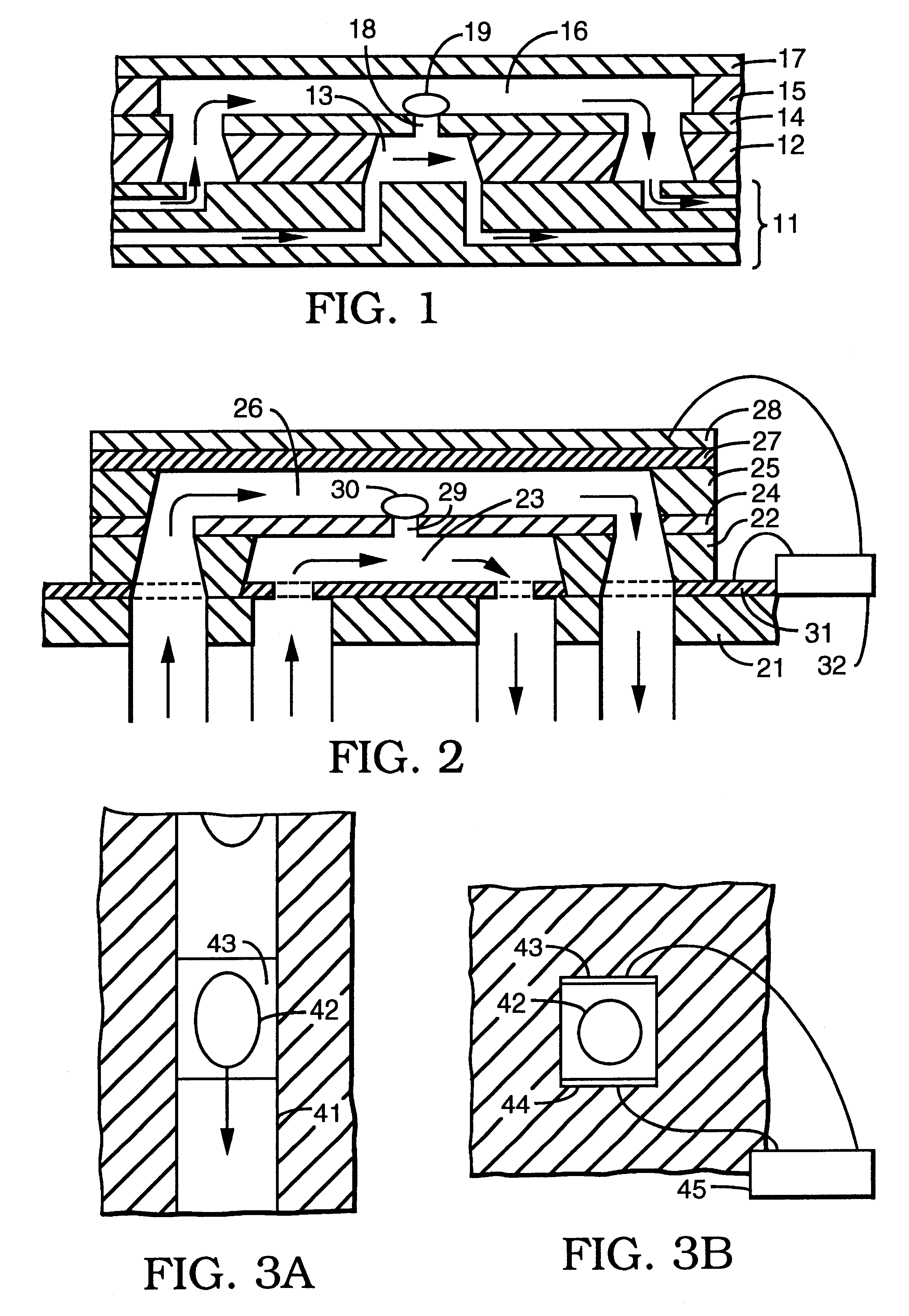
A series of experiments was performed using a microelectroporation system consisting of the microelectroporation device described above and shown in FIG. 2, combined with flow and pressure control units and pressure gauges for the liquids to be circulated through the upper and lower chambers, a variable DC power supply, a pulse generator and power amplifier for imposing voltage pulses across the device, a digital oscilloscope for monitoring the pulses, a fluorescent microscope, a CCD (charge coupled device) camera, and a computer with image processing and waveform processing software. Both chambers of the device were filled with physiological saline and cells were introduced into the upper chamber. Liquid motion in the top and bottom chambers was controlled by syringes. The pressure in the upper chamber was atmospheric while the pressure in the lower chamber was reduced below atmospheric by pulling on the barrel of the syringe connected to that chamber. The voltage was applied in si...

example 2

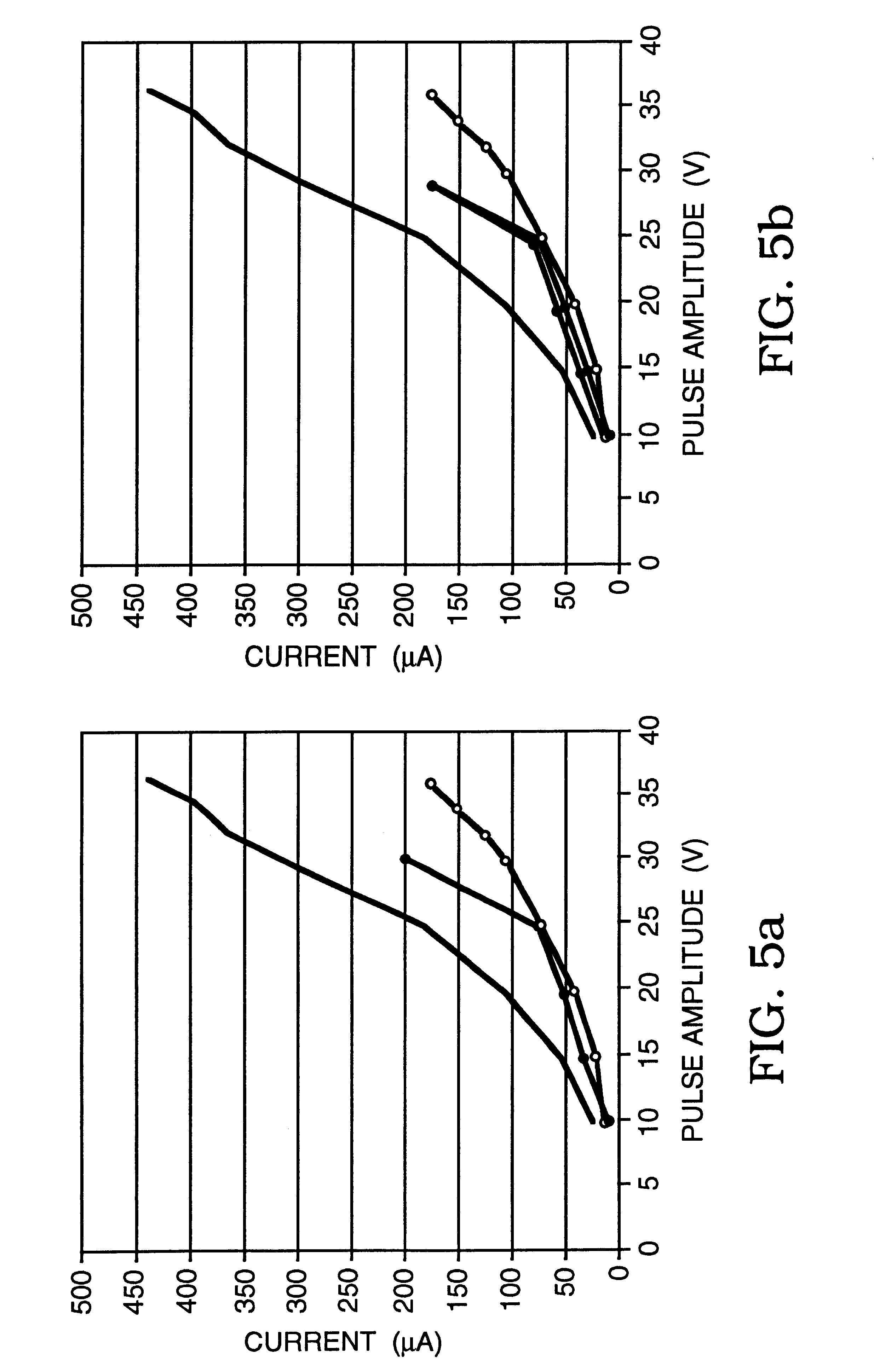
Using the same microelectroporation system used in Example 1, a series of tests were performed on rat hepatocytes (ATCC #CRL-1439), whose typical cell diameter was 20 microns, the microelectroporation apparatus having an opening that was 4 microns in diameter. Here as well, rectangular voltage pulses that were 60 milliseconds in duration were used, ranging in amplitude from 10V to 37.5V in increments of 5V in the portion from 10V to 30V and in increments of 2.5V in the portion from 30V to 37.5V. The experiments were performed in some cases only by increasing the amplitudes and in others by first increasing, then decreasing the amplitudes to evaluate reversibility. The results are plotted in the graphs shown in FIGS. 5a, 5b, 5c, and 5d. In each case, the upper curve (data points represented by circles) is the data taken with neither a cell nor a glass bead residing in the opening, the lower curve (data points represented by squares) is the data taken with a glass bead in the opening,...

example 3

Electrical Impedance Mapping of Electroporated Domains

In order to illustrate the ability of EIT to monitor electroporation in tissue we have solved a mathematical simulation of the problem.

To provide the necessary data for electroporation imaging simulation, a simulated tissue phantom was created first using a 2-D fine-mesh FEM model (.about.600 nodes, .about.3100 elements). The phantom, shown in FIG. 9, consisted of a circular imaging domain (20 mm radius, resistivity 500 ohm cm for muscle with a variable number of point source electrodes equally spaced around the periphery. Within this imaging region, a single arbitrarily shaped electroporated region was defined with a different resistivity. An opposite electrode current injection pattern was used, providing N(N-1) / 2 independent voltage measurements where N is the number of electrodes. The model was solved using the adaptive mesh generation and FEM solution algorithms available in MATLAB's Partial Differential Equation Toolbox (Th...


PUM

PropertyMeasurementUnit
diameteraaaaaaaaaa
diameteraaaaaaaaaa
diameteraaaaaaaaaa

Abstract

Images created by electrical impedance tomography (EIT) are used to adjust one or more electrical parameters and obtain a desired degree of electroporation of cells in tissue. The parameters include current, voltage and a combination thereof. The cells are subjected to conditions such that they become permeabilized but are preferably not subjected to conditions which result in irreversible pore formation and cell death. The electroporation can analyze cell membranes, diagnose tissues and the patient as well as to move materials into and out of cells in a controlled manner.

Description

This invention relates to the field of electroporation and mass transfer across cell membranes in general and the transport of ions across a cell membrane in particular.Electroporation is a technique that is used for introducing chemical species into biological cells, and is performed by exposing the cells to an electric potential that traverses the cell membrane. While its mechanism is not fully understood, electroporation is believed to involve the breakdown of the cell membrane lipid bilayer leading to the formation of transient or permanent pores in the membrane that permit the chemical species to enter the cell by diffusion. The electric potential is typically applied in pulses, and whether the pore formation is reversible or irreversible depends on such parameters as the amplitude, length, shape and repetition rate of the pulses, in addition to the type and development stage of the cell. As a method of introducing chemical species into cells, electroporation offers numerous ad...

Claims


Application Information

Patent Timeline
Patent Type & Authority Patents(United States)
IPC IPC(8): C12M3/00G01N33/487G01N27/02A61N1/30C12M1/00C12M1/42C12N5/07C12N5/071C12N13/00C12N15/09
CPCA61B5/0536G01N33/48728C12M35/02
Inventor RUBINSKY, BORISHUANG, YONG
Owner RGT UNIV OF CALIFORNIA
Why Eureka
Try Eureka