Electrode, method of producing electrode, and cell comprising the electrode

a technology of electrodes and electrodes, applied in the field of electrochemical equipment, can solve the problems of battery inability to suppress an increase in short-circuit current, further increase of short-circuit current, and exothermic reaction

Inactive Publication Date: 2002-06-04
MITSUBISHI ELECTRIC CORP
View PDF24 Cites 9 Cited by
  • Summary
  • Abstract
  • Description
  • Claims
  • Application Information

AI Technical Summary

Benefits of technology

A first electrode according to the invention is an electrode comprising an active material and an electron conductive material that is in contact with the active material, characterized in that the electron conductive material contains a conductive filler and a resin and is constituted so as to increase its resistivity with increasing temperature. According to this invention, since the electron conductive material contains a conductive filler and a resin and is constituted so as to increase its resistivity with increasing temperature, the electrode is capable of suppressing an increase of electric current when temperature rises.
A fifth process for producing an electrode according to the invention is the fourth process characterized in that the electron conductive material is pulverized under cooling. In this embodiment, an electron conductive material with further reduced size variation can be obtained by carrying out the pulverization while cooling. An electrode produced by using the thus pulverized electron conductive material has still higher flexibility and is therefore still easier to fabricate.

Problems solved by technology

However, on the safety valve's operation, moisture in the air enters the inside of the battery, which can induce an exothermic reaction in case lithium exists in the negative electrode.
When a short-circuit occurs in the inside of a conventional lithium secondary battery to raise temperature, the battery is incapable of suppressing an increase of the short-circuit current.
However, the part of the separator distant from the heat generating part does not always melt.
Besides, in case temperature rises, it is likely that the separator melts and flows to lose its function of electric insulation between positive and negative electrodes, which can lead to a short-circuit.
It follows that the battery temperature further increases by heat generation, which results in a further increase of the short-circuit current.

Method used


Image

  • Electrode, method of producing electrode, and cell comprising the electrode
  • Electrode, method of producing electrode, and cell comprising the electrode
  • Electrode, method of producing electrode, and cell comprising the electrode

Examples


example 2

Example 2 is characterized in that the electrode (positive electrode 1) was prepared in the same manner as in Example 1, except that the positive electrode active material paste was applied on aluminum foil, dried at 80.degree. C., and pressed at 135.degree. C. under a pressure of 0.5 ton / cm.sup.2 for 30 minutes. The negative electrode was prepared in the same manner as in Example 1. The characteristics of the resulting electrode and the battery having the electrode are shown in FIG. 9.

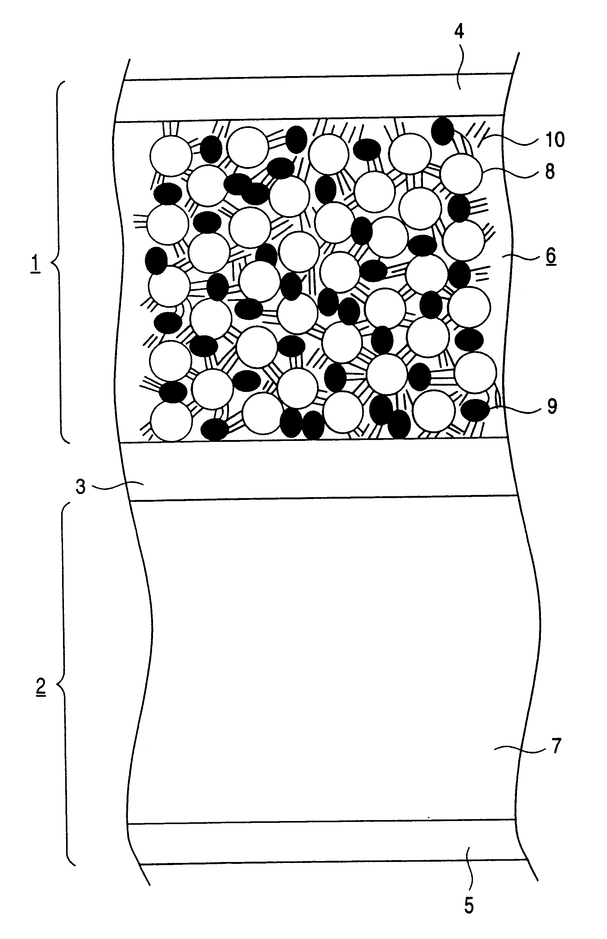
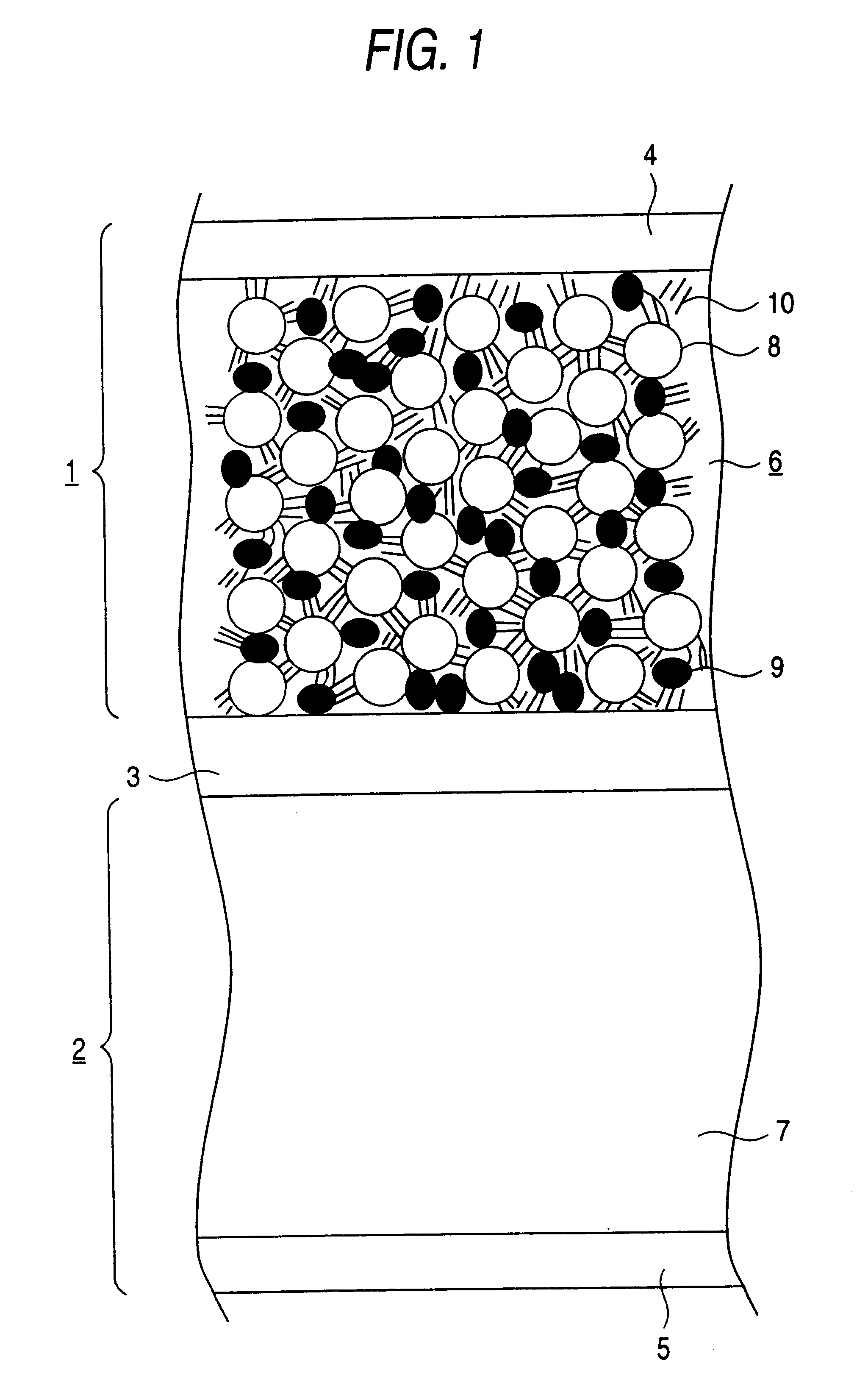
Because in Example 2 the dried paste is pressed at around the melting point of the resin contained in the electron conductive material 9, the adhesion between the current collector 4 and the active material layer 6 is improved thereby to reduce the contact resistance between the current collector 4 and the active material layer 6 as shown in the Figure. Further, the particles of the electron conductive material 9 deform and spread among the particles of the active material 8, while improving connectio...

example 3

Preparation of Positive Electrode:

An electron conductive material having a volume resistivity of 0.2 .cndot..multidot.cm at room temperature and of 500 .cndot..multidot.cm at a working temperature of 135.degree. C. (e.g., pellets comprising carbon black and polyethylene in a prescribed ratio) was pulverized by a jet mill method to prepare fine particles of the electron conductive material having an average particle size of 9.0 .mu.m.

Four-point-five parts by weight of the fine particles, 1.5 parts by weight of artificial graphite KS-6 (produced by LONZA Ltd.) as a conducting agent, 91 parts by weight of an active material (e.g., LiCoO.sub.2), and 3 parts by weight of a binder (e.g., PVDF) were dispersed in NMP, a dispersing medium, to prepare a positive electrode active material paste.

The paste was applied to a 20 .mu.m thick metal film (aluminum foil) serving as a positive electrode current collector 4 by a doctor blade coating method, dried at 80.degree. C., and pressed at a prescr...

example 4

Example 4 is characterized in that the positive electrode was prepared in the same manner as in Example 1, except that the electron conductive material was ground by a combined method and then further pulverized by a jet mill method. The negative electrode of Example 4 was prepared in the same manner as in Example 1.

FIG. 11 is a table showing average particle size of the electron conductive material used in the electrode (positive electrode 1) of Example 4. It is seen that the average particle size of Example 4 is smaller than in Example 1. Since the electron conductive material is reduced in size by a combined pulverizing method and then further pulverized by a jet mill method, the resulting particles of the electron conductive material have a reduced particle size with reduced variation of particle size, and the time required for pulverization can be shortened. Accordingly, an electrode prepared by using the resulting electron conductive material is highly flexible and easy to fab...


PUM

PropertyMeasurementUnit
melting pointaaaaaaaaaa
particle sizeaaaaaaaaaa
temperatureaaaaaaaaaa

Abstract

An electrode for a battery which increases resistivity with increasing temperature. The electrode has an electron conductive material containing a conductive filler and a resin so as to increase its resistivity with increasing temperature. This solves the problem of the prior art where the battery temperature rises above a temperature at which the separator melts and flows due to an internal short circuit, with a large short circuit current being generated between the positive and negative electrodes at portions where the separator flows to cause heat generation to further increase the battery temperature. As a result, the short circuit current increases further.

Description

This invention relates to an electrode, a process for producing the same, and a battery using the same. More particularly, it relates to an electrode which increases its resistivity with increasing temperature, a process for producing the electrode, and a battery having the electrode.DISCUSSION OF THE BACKGROUNDWith the recent development of electronic equipment, batteries used therein as a power source have increasingly gained in capacity and output density. A lithium ion secondary battery is attracting attention as a battery fulfilling these requirements. A lithium ion secondary battery has an advantage of high energy density but requires sufficient safety measures because of the use of a nonaqueous electrolytic solution.Conventionally proposed safety measures include a safety valve which relieves inner pressure increases and a PTC element which increases resistivity on heat generation due to an external short-circuit to shut off the electric current. For example, incorporation of...

Claims


Application Information

Patent Timeline
Patent Type & Authority Patents(United States)
IPC IPC(8): H01M4/02H01M10/36H01M10/48H01M10/40H01M4/58H01M4/04H01M4/62H01M10/42H01M2/34H01M2/20H01M6/00H01M6/50H01B1/00H01B1/16H01M4/13H01M4/131H01M4/1391H01M6/16H01M10/05H01M10/0525H01M10/0566
CPCH01M2/348H01M4/04H01M4/0416H01M4/043H01M4/131H01M4/1391H01M4/62H01M4/624H01M10/4235Y02E60/122H01M4/0402H01M4/625H01M6/16H01M10/0525H01M2004/021H01M2200/106H01M4/02H01M50/581Y02E60/10
Inventor KISE, MAKIKOYOSHIOKA, SHOJIARAGANE, JUNURUSHIBATA, HIROAKISHIOTA, HISASHIHORIBE, HIDEOAIHARA, SHIGERUTAKEMURA, DAIGO
Owner MITSUBISHI ELECTRIC CORP
Why Eureka
Try Eureka