Method and apparatus for performing localized thermal analysis and sub-surface imaging by scanning thermal microscopy

Inactive Publication Date: 2002-12-10
WATERS TECH CORP
View PDF13 Cites 71 Cited by
  • Summary
  • Abstract
  • Description
  • Claims
  • Application Information

AI Technical Summary

Benefits of technology

Another object of the present invention is to provide an apparatus which can, for a sample containing different regions subject to either reversible or irreversible changes with temperature, produce thermal images showing contrast based upon the reversing and nonreversing nature of the heat flow, respectively.
FIG. 1 illustrates schematically a resistive thermal probe 100 for use in a preferred embodiment of the present invention. The probe 100 comprises a cantilever 102 mounted to a cantilever mount 104. The arms of the cantilever are made of Wollaston process wire having silver wire that is preferably 75 .mu.m in diameter. The silver wire preferably contains a platinum / 10% rhodium core. The platinum / rhodium core is preferably 5 .mu.m in diameter. The arms of the cantilever form a loop 106 at one end of the probe 100. Where the loop 106 is formed, the silver is etched away, thereby exposing the platinum / 10% rhodium core. The length of the exposed core is preferably 150-200 .mu.m in length. The loop 106 is the resistive heating source of the probe 100. As shown in FIG. 1, the cantilever 102 of the probe 100 is bent to a suitable shape, i.e., has as sharp a bend as possible. The sharp bend yields a very small area of contact with the sample. The small area of contact with the sample allows for precise heating of a particular location on the sample. Such a probe 100 is commercially available from the Topometrix Corporation.

Problems solved by technology

These discrepancies arise from approximations and assumptions in the model and also because the sample geometry is not yet fully controllable.

Method used


Image

  • Method and apparatus for performing localized thermal analysis and sub-surface imaging by scanning thermal microscopy
  • Method and apparatus for performing localized thermal analysis and sub-surface imaging by scanning thermal microscopy
  • Method and apparatus for performing localized thermal analysis and sub-surface imaging by scanning thermal microscopy

Examples


example 1

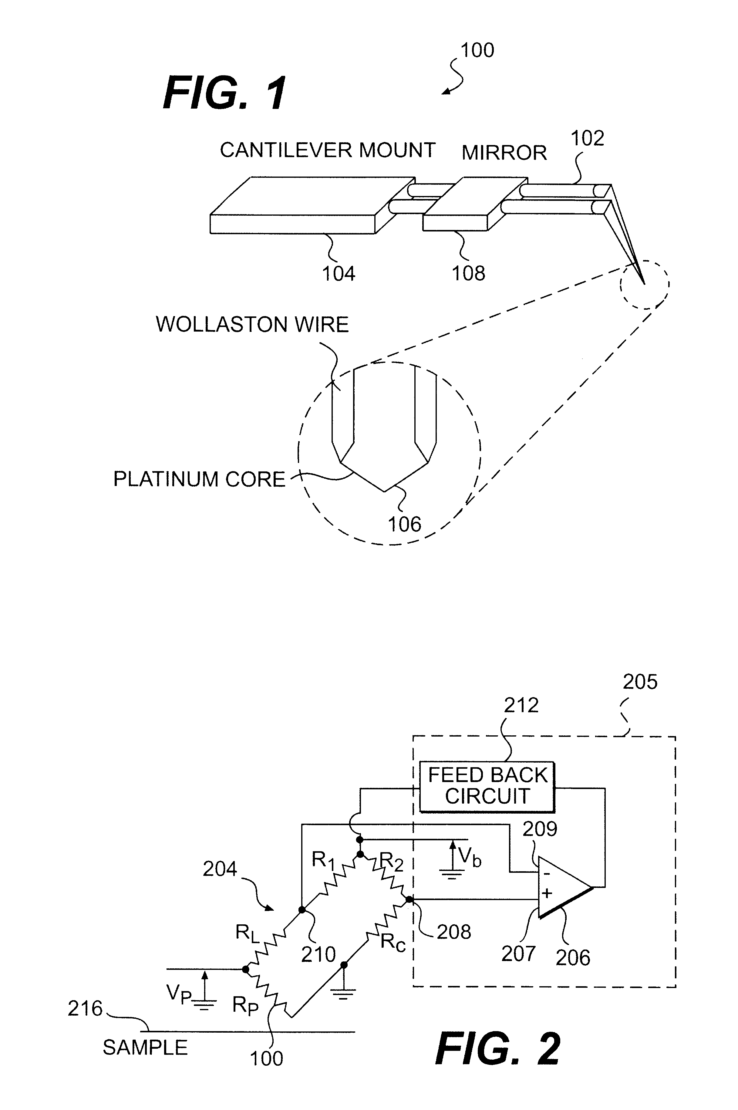
This example illustrates the use of the present invention to map heterogeneous samples with heterogeneous thermal properties. FIGS. 11A, 11B, 11C and 11D were obtained with the scanning probe microscope of the present invention operated in the constant temperature mode and the probe temperature set at 40.degree. C. The thermal contrast images were computer-generated, using the feedback voltage V.sub.b applied to the Wheatstone bridge circuit 204. Because of the relatively slow scan speed (usually 100 .mu.m s.sup.-1), steady state (thermal equilibrium between the probe and the region of the sample whose temperature is affected by the probe) was reached at each point, so that the image contrast was indeed determined by the value of the heat flow. At each sampling point a certain volume of material was heated. This volume can be approximately delimited by the thermal contact area and an effective depth determined by the temperature gradient below that contact area. The heat flow from t...

example 2

This example demonstrates the use of the present invention for the study of immiscible polymer blends systems, including a Poly(vynil chloride) [PVC] / Polybutadiene [PB] blend, a Poly(ethylene oxide) [PEO] / Polybutadiene [PB] blend and a Poly(methyl methacrylate) [PMMA] / Chlorinated polyethylene [CPE] blend. The blends were cast from solutions on microscope glass covers with a 50 / 50 percentage weight. After drying, films about a hundred microns thick are formed.

In each system, the two polymers involved segregate, being immiscible: one forms a matrix and the other forms island-like domains. The two phases in each sample were identified by mapping the thermal conductivity variation across the surface of the sample using the thermal probe, operated in the closed loop mode at a constant temperature of 40.degree. C. The signal was obtained from the feedback voltage applied to the controlling bridge in order to maintain a constant probe temperature. The contrast at each point represents vari...

example 3

This example illustrates the use of the present invention to follow, in real time, the behavior of PVC domains in a PVC / PB blend as a function of temperature, using a temperature-controlled hot stage. The same area was scanned at increasing hot stage temperature, which was maintained constant during each scan. The probe was operated in the closed loop mode, at a constant temperature of 85.degree. C. Images obtained at room temperature (RT), 50.degree. C., 70.degree. C., 78.degree. C., 95.degree. C. and 100.degree. C. are shown in FIG. 14A (1402, 1404, 1406, 1408, 1410 and 1412). (The temperature of the sample is shown in the upper right-hand corner of each image.) FIG. 14B also shows images (1420, 1422, 1424, 1426, 1428 and 1430) of PVC domains in a PB matrix as a function of increasing temperature. As the temperature is increased up to about 70.degree. C., little change to the system is observed, although small domains can be seen to move and are absorbed into neighboring larger on...


PUM

PropertyMeasurementUnit
diameteraaaaaaaaaa
diameteraaaaaaaaaa
lengthaaaaaaaaaa

Abstract

A platinum / Rhodium resistance thermal probe is used as an active device which acts both as a highly localized heat source and as a detector to perform localized differential calorimetry, by thermally inducing and detecting events such as glass transitions, meltings, recystallizations and thermal decomposition within volumes of material estimated at a few mum3. Furthermore, the probe is used to image variations in thermal conductivity and diffusivity, to perform depth profiling and sub-surface imaging. The maximum depth of the sample that is imaged is controlled by generating and detecting evanescent temperature waves in the sample.

Description

1. Field of the InventionThe present invention relates to determining thermal properties of materials using a miniaturized resistive thermal probe. More particularly, the present invention relates to performing localized thermal analysis experiments whereby calorimetric information is obtained from a volume of materials on the order of a few cubic microns, whereas in conventional bulk calorimetry data is obtained from volumes of material on the order of a few cubic millimeters. The present invention also relates to modulating the temperature of a thermal probe to generate evanescent thermal waves in a material to thereby generate sub-surface images.2. Background of the InventionSeveral methods for the non-destructive characterization of solids make use of thermal excitation. Any local disruption of the structure that results in a change in density, specific heat, or thermal conductivity may be detected by some type of thermal probe--often with higher sensitivity than by the use of o...

Claims


Application Information

Patent Timeline
Patent Type & Authority Patents(United States)
IPC IPC(8): G01N25/20G01N25/48G01Q60/58
CPCB82Y35/00G01N25/4833G01Q60/58Y10S977/732Y10S977/867Y10S977/957Y10S977/852Y10S977/86Y10S977/869Y10S977/881Y10S977/849
Inventor HAMMICHE, AZZEDINEMONTAGU-POLLOCK, HUBERT MURRAYREADING, MICHAELSONG, MO
Owner WATERS TECH CORP
Why Eureka
Try Eureka