Binary self-correcting phase detector for clock and data recovery

a phase detector and clock technology, applied in the field of data transmission and communication systems, can solve the problems of limiting the link to work only at a single data rate, high q bandpass filter cost, and clock signal is necessary to retime or regenerate the received data,

Inactive Publication Date: 2003-06-10
IBM CORP
View PDF13 Cites 32 Cited by
  • Summary
  • Abstract
  • Description
  • Claims
  • Application Information

AI Technical Summary

Problems solved by technology

However, the clock signal is necessary to retime or regenerate the received data which is typically corrupted by noise due to the physical medium and electronic and / or optical devices in the case of a transmission over an optical (e.g., glass) fiber.
However, these high Q bandpass filters are generally expensive and limit the link to work only at a single data rate.
Also, direct extraction techniques are difficult to integrate therein.
As frequencies become higher, time delays inherent in digital circuits become more significant compared to the bit interval.
At very high speeds (e.g., a few GHz to tens of GHz), a misalignment of even a few picoseconds can dramatically increase the transmission system's bit error rate.
Linear PDs may not work well at extremely high bit rates because they must generate relatively narrow pulses compared to the bit interval as the phase error becomes smaller.
Consequently, they suffer from a relatively large static phase error which is not desirable for optimum sampling of the received data.
For high speed applications, these complex architectures have two major drawbacks: power consumption and layout complexity.
Indeed, circuit performance is very sensitive to layout parasitics at high frequency operation.
The parasitic elements associated with interconnect wires cause loading and coupling effects that degrade the frequency behavior and the noise performance of the circuits.

Method used


Image

  • Binary self-correcting phase detector for clock and data recovery
  • Binary self-correcting phase detector for clock and data recovery
  • Binary self-correcting phase detector for clock and data recovery

Examples


first embodiment

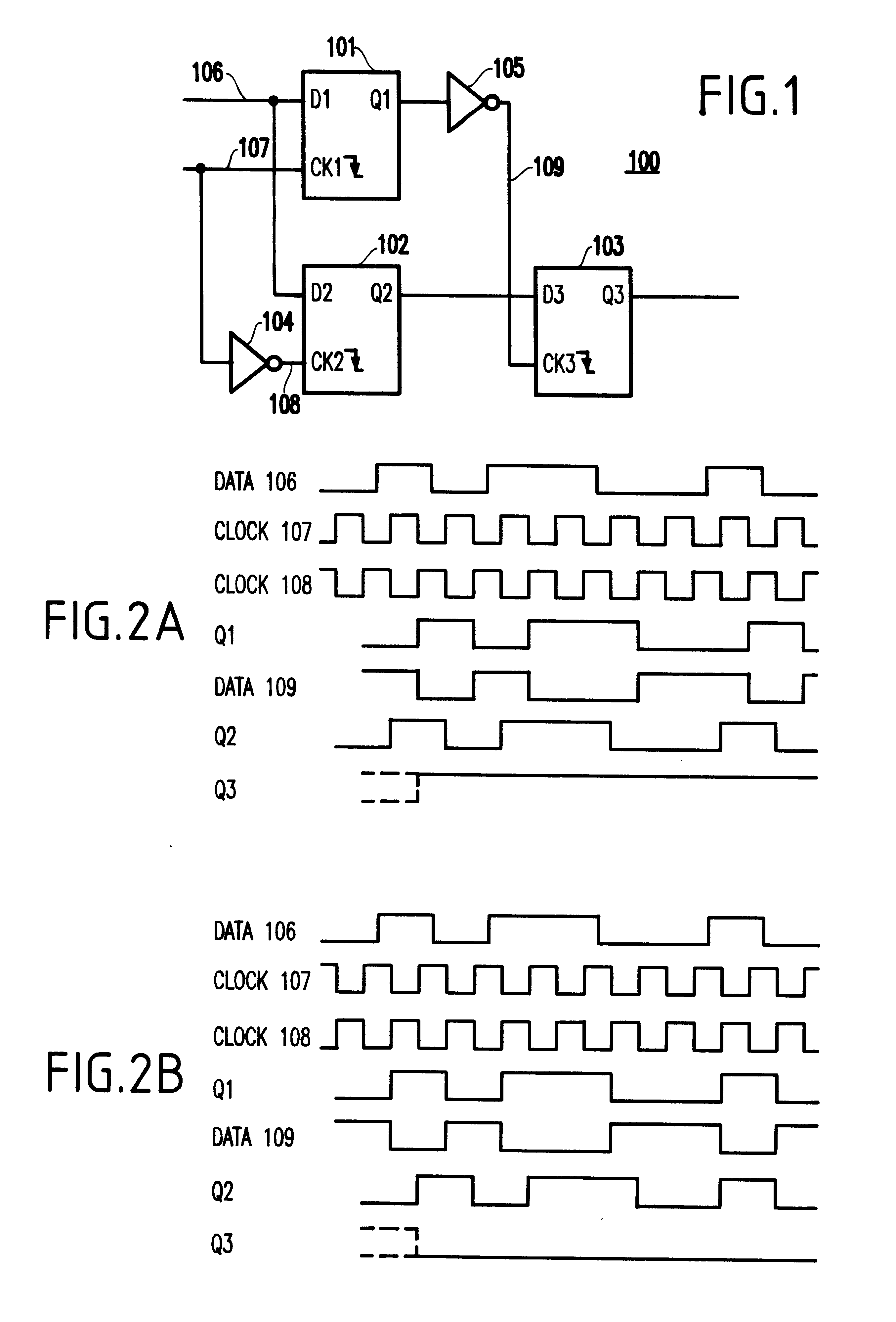
Referring to FIGS. 1-2B, a first embodiment of the present invention will be described below.

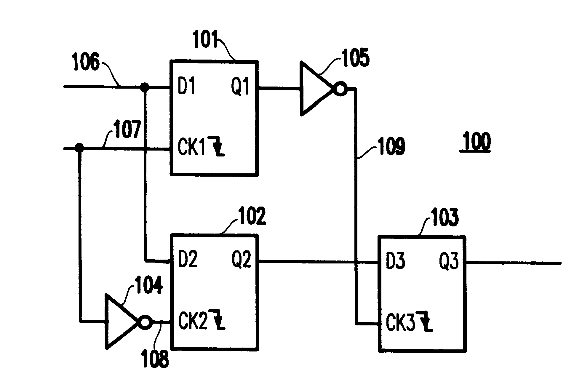
FIG. 1 illustrates the structure of a phase detector 100 according to the first embodiment of the present invention. The phase detector 100 includes a plurality (e.g., preferably three) of falling edge-triggered flip-flops 101, 102 and 103.

A random data stream 106 is received in the data input D1 of flip-flop 101 and in the data input D2 of flip-flop 102. It is noted that the invention is optimized with a Non-Return-to-Zero (NRZ) data stream in which the bit period is matched to the frequency of the clock.

The phase detector 100 also includes an inverter 104 for receiving a clock signal 107 from a clock generator (not illustrated) to produce an inverted phase clock signal 108. The clock signal 107 and the inverted phase clock signal 108 are applied to the clock input CK1 of flip-flop 101 and to the clock input CK2 of flip-flop 102, respectively, thereby causing the: received data signal 106 t...

second embodiment

Referring to FIG. 3, a second embodiment of the invention will be described below.

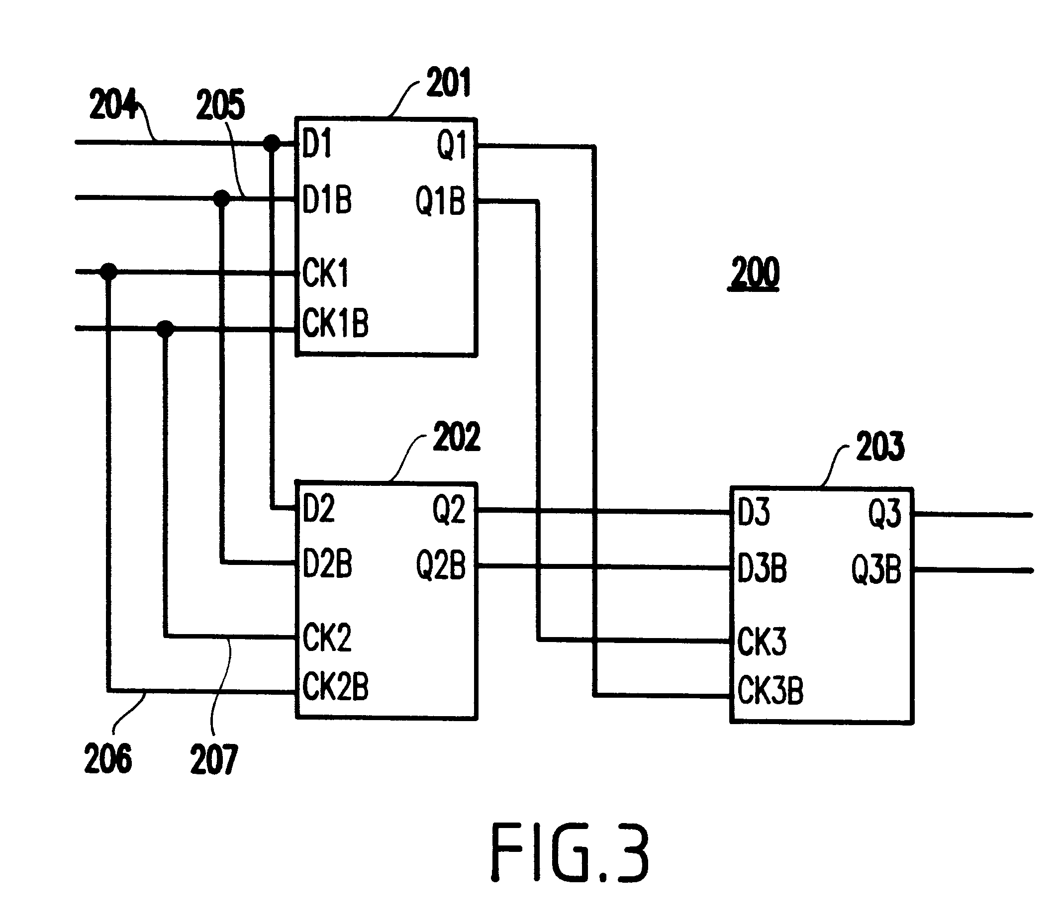
FIG. 3 illustrates a phase detector 200 according to the second embodiment of the present invention using differential logic. The phase detector 200 comprises a plurality (e.g., preferably only three; but additional ones could be added, to reduce metastability, at the stage of receiving the incoming data stream) of edge-triggered flip-flops 201, 202 and 203, each one preferably having differential data and clock inputs and differential outputs.

A NRZ random data stream 204 and its complementary signal 205 are received respectively, in the complementary data inputs D1 and D1B of flip-flop 201. Complementary data signals 204 and 205 are also received, respectively, in the complementary data inputs D2 and D2B of flip-flop 202.

The clock signal 206 and its complementary signal 207 are applied, respectively, to the complementary clock inputs CK1 and CK1B of flip-flop 201. Complementary clock signals 206 and 2...


PUM


Abstract

A phase detector for a clock and data recovery circuit from random non-return-to zero (NRZ) data signal includes a plurality (e.g., preferably three) edge-triggered flip-flops. The incoming NRZ data are sampled by a pair of edge-triggered flip-flops using the transition of the clock generated by the clock recovery circuit. A third edge-triggered flip-flop processes the outputs from the edge-triggered flip-flop pair to indicate whether the generated clock leads or lags the received data.

Description

1. Field of the InventionThe present invention generally relates to data transmission and communication systems, and more particularly to a phase detector used in a clock recovery system for recovering a clock signal from transmitted NRZ (non-return-to-zero) data. Also, the phase detector of the present invention provides the retimed or regenerated data directly from the transmitted NRZ data utilizing the recovered clock signal.2. Description of the Related ArtWhen data are transmitted over a communication link, the associated clock signal is generally not transmitted, thereby providing for better efficiency of the link. However, the clock signal is necessary to retime or regenerate the received data which is typically corrupted by noise due to the physical medium and electronic and / or optical devices in the case of a transmission over an optical (e.g., glass) fiber. The clock signal also provides timing necessary for subsequent digital circuitry such as demultiplexers or framers. T...

Claims


Application Information

Patent Timeline
Patent Type & Authority Patents(United States)
IPC IPC(8): H03D13/00
CPCH03D13/003
Inventor MEGHELLI, MOUNIR
Owner IBM CORP
Why Eureka
Try Eureka