
Dynamic consolidation of powders using a pulsed energy source

Inactive Publication Date: 2004-07-27
UTRON KINETICS
View PDF11 Cites 51 Cited by
  • Summary
  • Abstract
  • Description
  • Claims
  • Application Information

AI Technical Summary

Benefits of technology

Still another object of this invention is to provide a method and apparatus for consolidating nanophase or nanosized powders (be they magnetic or non-magnetic) at substantially room temperature or at temperatures of a few hundred degress Celsius, and to perform the consolidation during a time so short that grain growth is reduced or eliminated altogether.
In most of the configurations, operation without using diaphragms to contain the prefill combustible gas is possible. It is only necessary to have a tight fitting piston or other seal to prevent the combustible gases from leaking into the precompaction powders, which in general would be undesirable. It appears to be desirable to provide a mechanism for pumping out any gases within the powder prior to compaction. This can be accomplished using a small vacuum pump and access holes, or by loading the powder into the compaction chamber while under vacuum.

Problems solved by technology

However, the high cost of powder metallurgy technology must compete with other low cost manufacturing methods.
In practice, the available materials must compromise some of these properties in favor of others.
For example, the eddy current losses arise because soft magnetic materials generally operate in alternating fields.
The losses arise primarily because of difficulties in reversing the magnetization state of the material.
The eddy current losses also increase as the size of the magnetic regions increases and as the resistivity decreases.
Practically, the consolidation of nanocrystalline and amorphous particulate into useful engineering devices provides many unique challenges.
However, exposure to elevated temperatures significantly degrades the hard-won microstructural features through crystallization and grain growth.
Using binders, however, dilutes the amount of magnetic material in the final part to, at most, 70 percent by volume, resulting in a lower saturation magnetization by volume in the final engineering component.
Most dynamic consolidation techniques, however, are not amenable for large-scale production techniques.
This multiple domain state leads to relatively easy demagnetization and poor hard magnetic properties.
Because of this requirement of a fine grain size, non-equilibrium processing techniques are required.
However, during the relatively prolonged times at elevated temperatures, grain growth occurs, resulting in deleterious effects on the magnetic properties.
Die upsetting results in crystallographic alignment through preferred grain growth.
However, the additional exposure to elevated temperatures during die upsetting further degrades the microstructure.
These dynamic consolidation processes result in extremely short exposure to elevated temperatures, allowing the fine microstructures generated during melt spinning to be retained.
However, scale-up of the previously mentioned dynamic consolidation techniques provide unique challenges.
Intermetallic compound powders made by rapid solidification processing (RSP) are brittle and hard, making it difficult to consolidate these powders by conventional techniques.
The high temperature exposures for long times, involved in the conventional techniques, causes excessive grain growth and phase transformation of the initially RSP microstructure.
Also, room-temperature brittleness is a problem with conventional intermetallics.
The challenge, then, is to develop powder consolidation techniques that do not adversely affect any enhancements due to RSP.
These are all very large, noisy, complex, and expensive systems.
The limitations of conventional die pressing include limited green density, limited green strength, green density gradients, need for binders and binder removal (a slow and expensive process), and shrinkage of parts during sintering.
While higher green densities with less density gradients are reached at a given pressure when compared to die pressing, most of the other limitations of die pressing exist in CIP.
The long time exposures at high temperatures lead to grain growth and loss of the initial fine and rapidly solidified microstructures.
A disadvantage with reactive sintering is the difficulties associated with HIP, which often accompanies or succeeds reactive processing, such as the need for ductile canning materials that do not react with the powders and the need to seal cans carefully.
However, the principal disadvantages are the difficulty of complete binder removal and the inability to produce continuous fiber-reinforced composites.
Such temperatures are difficult to achieve by other powder-vehicle compaction methods that require transfer of either a preheated preform or the heated medium into the compaction vessel.
As the shock wave passes through the powder, it gives up most of its energy at particle boundaries, possibly because of interparticle friction.
The same composite when hot pressed resulted in a thick (more than 1 micrometer) fiber / matrix reaction zone that is deleterious to the fracture properties of the composite.
Consolidation occurs so rapidly that there is not enough time to re-establish equilibrium.
For example, some powders are so brittle that conventional isostatic pressing may cause excessive particle fractures.
Cracking is another problem that must be solved.
Also, the rarity of kinetic energy storage machines and the small sizes of samples produced to date make it difficult to predict whether kinetic energy discharge is a commercially viable way to consolidate powders.
One limitation of DMC is the general need for post sintering, under a reducing atmosphere such as hydrogen, or HIP to complete grain bonding.
Note that the quoted peak pressure of 1400 MPa apparently leads to damage to the coil, and a consequently limited lifetime.
Making survivable coils which can operate repetitively at pressures above 5-6 kbar is difficult.
All known techniques, both static and dynamic, are in general not cost effective compared to conventional wrought processing techniques and none of the dynamic techniques have generated any significant commercial activity.
In fact, almost any combination of combustible gas mix and diluent could be used, but practical choices are typically limited to methane, oxygen, and a diluent gas consisting of argon, helium, or nitrogen.
However, unlike one use projectile seals this seal operates repeatedly.
Although higher pressures are possible, it is generally desirable to run the device at the lowest pressure consistent with the desired ram load as this prolongs the chamber fatigue life.
It is only necessary to have a tight fitting piston or other seal to prevent the combustible gases from leaking into the precompaction powders, which in general would be undesirable.
Lower energies lead to long slow burn rates initially.
There is one case, however, where sharp shock waves could be produced, and that is when a detonation of the combustible gas mix occurs.
The high power arc quickly heats the gas, causing the pressure to rise to a high value, bursting the diaphragm and forcing the pusher piston to compact the powders.
This cannot be achieved in practice because of parasitic losses in the switch and leads, but these losses are typically small.
The combustion technique is probably the approach of choice when very large energies are required for large compacts, since providing pulsed electrical energies of tens or hundreds of Megajoules is difficult and expensive, but easy and cheap with chemically supplied energy in the form of combustible gases.
The production rate limiting factor is expected to be the time required to insert powders into the die and subsequent removal of the consolidated part afterwards.
Die life may be high even at relatively high loads due to the short time duration of the pressure.
However, unlike one-use projectile seals, this seal operates repeatedly.
Although higher pressures are possible it is generally desirable to run the device at the lowest pressure consistent with the desired ram load as this prolongs the chamber fatigue life.

Method used


Image

  • Dynamic consolidation of powders using a pulsed energy source
  • Dynamic consolidation of powders using a pulsed energy source
  • Dynamic consolidation of powders using a pulsed energy source

Examples


example 2-- 30

Example 2--30 Ton Press

Testing in the second CDDC prototype, shown in FIG. 19, revealed the CDDC process to be both robust and versatile at compacting various types of powder materials. This larger CDDC device applied up to 300,000 pounds per square inch (150 tons per square inch) to one-half inch outer diameter, 5 / 8 inch inner diameter, ring shaped compacts of various materials, as shown in Table 3. FIG. 20a shows the same device with a volume filler to change the volume of the combustible gas. FIGS. 20b, c and d show additional detail of the compaction chamber, seals, ignitor, and pressure sensor. FIG. 21 shows photographs of two views of the hardware.

Typical ring compacts are shown in FIGS. 22 and 23. The compaction chamber configuration and the ring die set are shown in FIG. 24. Typical combustion and compaction pressures along with densities and mechanical properties for stainless steel powders compacted by the enhanced CDDC press are shown in FIG. 25. Properties for one of the...

example 3-- 300

Example 3--300 Ton Press

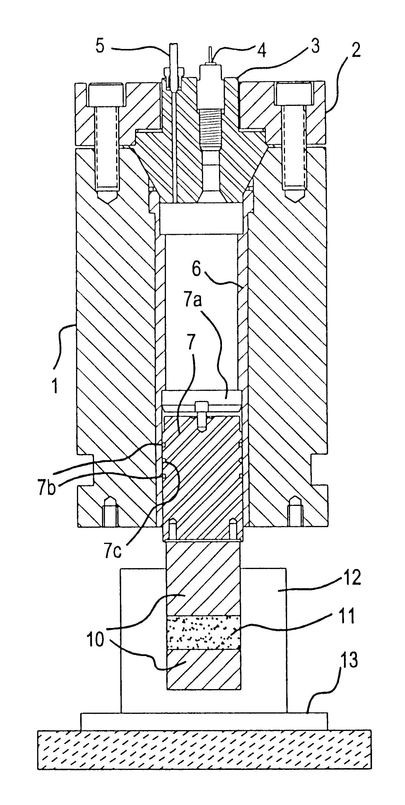
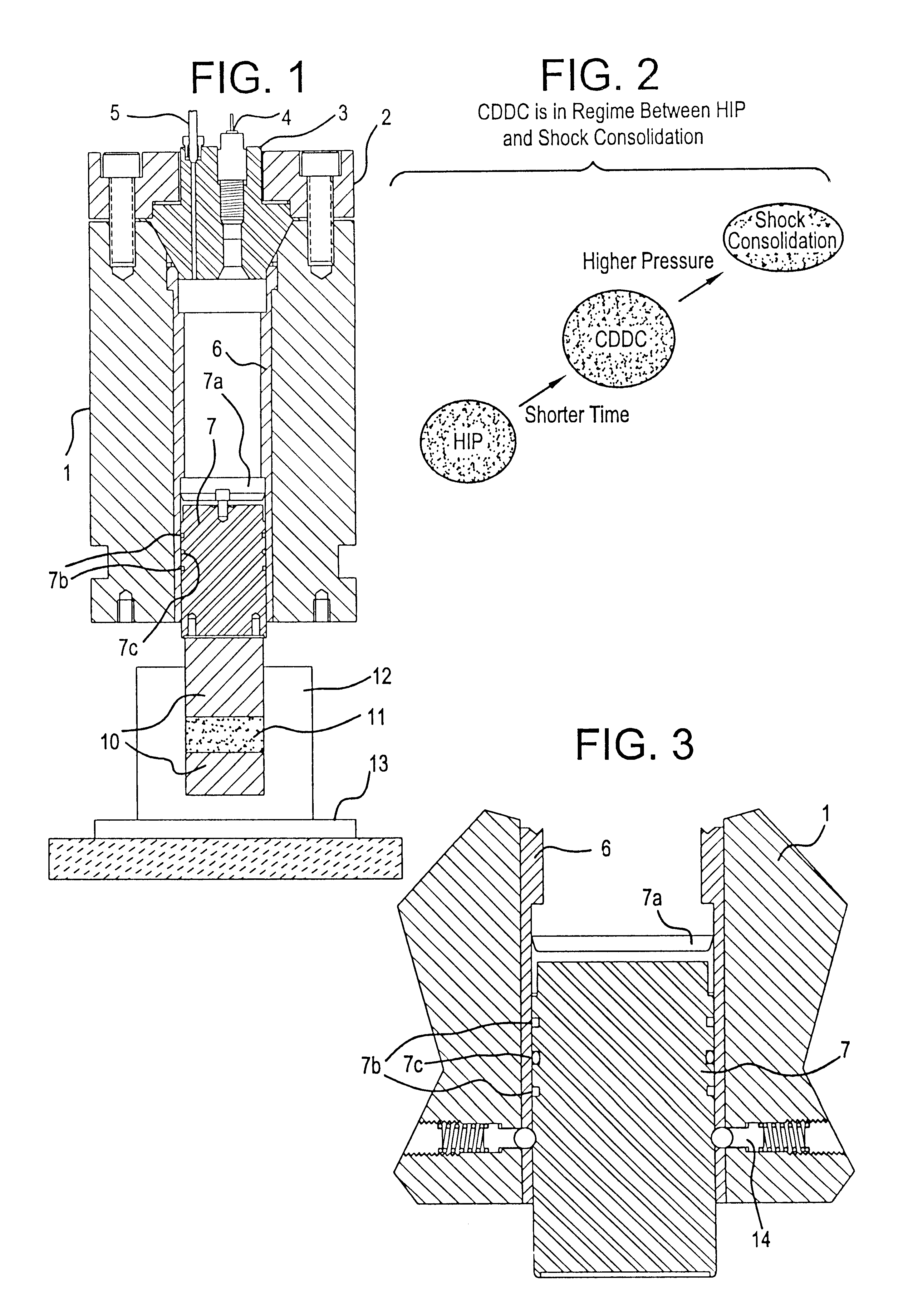
A third and larger prototype CDDC press further shows the versatility and performance capability of CDDC presses and technology. The internal details of this press were shown previously in FIG. 1. Externally the press looks as shown in FIGS. 29a and 30a, b, and c. Shown there also is the steel framework which supports the compaction unit above the die table. To the left is the cabinet containing the gas pumping system.

This 300-ton press has compacted standard Metal Powder Industries Federation (MPIF) standard 10 tensile test bars of various materials at pressures exceeding 300,000 pounds per square inch (150 tons per square inch). A typical test bar of 1 square inch surface is shown in two views in FIG. 31.

As seen in FIG. 1 the 300-ton CDDC press is mounted in the more traditional vertical orientation and uses standardized die sets placed under the press on the incorporated table. The sealing system for the ram has also been substantially improved as shown in...

example 4-- 3000

Example 4--3000 Ton Press

A dynamic compaction press design capable of delivering 3000 tons is shown in FIG. 29B in proper scale to the 300-ton press shown in FIG. 29A. Note that this press, although large relative to the previous examples, is still much smaller than conventional mechanical or hydraulic presses of this capacity. For example a conventional 3000-ton press may stand 30 feet tall and have a footprint of 400 square feet while a 3000-ton CDDC press would be about 10 feet tall and 100 square feet respectively. Combustion driven compaction devices are by nature relatively compact as the necessary energy is directly converted from the chemical state. It is expected that even larger output presses using the CDDC process are both feasible and relatively compact. It is also expected that such presses will be inexpensive relative to conventional presses.

Pressure Profile Control

In all embodiments of the invention, diaphragms, fast valves and adjustable diameter exhaust ports or or...


PUM

PropertyMeasurementUnit
Pressureaaaaaaaaaa
Temperatureaaaaaaaaaa

Abstract

A gas operated part forming die apparatus has compact high tonnage presses which are operated by high pressure gas generated within chambers and controlled to operate high pressure pistons and dies for compressing particulate material into dense formed parts. Combustion chambers are filled with pressurized mixtures of combustible gases and diluents. Elongated chambers have insulating walls and spaced electrodes. Some contain liquid or particulate ablatable materials or ablatable liners. Others extend fuzes between the electrodes and are filled with pressurized gases. Gas is removed from the particulate material. Die cavities may be precompressed during filing of chambers with pressurized gas. Igniting the combustible gases or creating arcs between the electrodes produces rapidly expanding high pressure resultant gases for driving pistons and movable dies and rapidly compressing die cavities. Pressures in the chambers are contained, or pistons are restrained until releasing and driving the pistons. Large area pistons drive smaller movable dies.

Description

1. Field of the InventionThis invention relates in general to the field of powder metallurgy and in particular to an improved and less expensive method and apparatus for generating controllable pressure pulses (both in the shock regime and in a rapid, but shock-free, regime in the same device) for the purpose of consolidating (compacting) powders to a contiguous rigid form, primarily for the purpose of producing material samples and manufactured parts. In this field, the emphasis is generally on producing higher quality and better performing parts, which generally means parts with higher density, strength and ductility, and doing so at lower cost.2. Description of Related ArtPowder metallurgy (P / M) offers possibilities for the design of materials into near net shape which exhibit a wide range of unique and novel properties. In principle, there is no limitation on the production of a material with any desired composition by such methods. However, the high cost of powder metallurgy te...

Claims


Application Information

Patent Timeline
IPC IPC(8): B22F3/087B30B11/02B30B1/00B30B11/00B01J3/06B01J3/08B22F3/08
CPCB22F3/087B30B1/002B30B11/001B30B11/02B22F2998/00B22F2998/10B29C43/003B29C43/361B29C2043/3266B29C2043/3618B29C2043/3628B29C2043/3636B29C2791/008B22F3/02B30B15/0017
Inventor WITHERSPOON, F. DOUGLASMASSEY, DENNIS W.MOZHI, T. ARULKRUCZYNSKI, DAVID L.RYAN, JOHN M.
Owner UTRON KINETICS
Learn More