
Electrochemical energy storage device of high specific power and electrodes for said device

Inactive Publication Date: 2005-01-18
MIRZOEV RUSTAM AMINOVICH +3
View PDF0 Cites 25 Cited by
  • Summary
  • Abstract
  • Description
  • Claims
  • Application Information

AI Technical Summary

Benefits of technology

The problem being solved with the present invention is how to enhance the service life period (increase in number of recharge cycles) and exclude the ecological harmful cadmium as structural material without decreasing the specific power and energy.
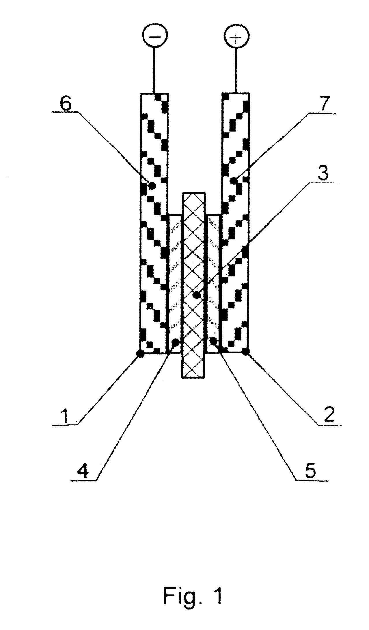
As a result of realization of the features of the invention new important properties of the energy storage device are achieved. The new arrangement of active material inside the metal collector brings on a number of important consequences, which radically change the properties of electrodes and of energy storage devices as a whole. In particular, there is no contact resistance between the collector and the active material and loss of electronic contact between the collector and the particles of active material is impossible as well as are flaking and peeling off of the active material from the collector. All this makes it possible to create extremely thin electrodes which is the main direction for increasing specific power.
It is just these fundamentally new properties of electrodes that permit to accomplish, in the framework of the claimed embodiments, the set task of enhancement of service life (increase in number of recharge cycles) without decrease (even with increase) in specific power and energy. In particular, absence of contact resistance “collector-active material” in the electrodes and low resistance of active material permit to increase specific power, impossibility of flaking and peeling off of active material from the collector and impossibility of loss of electronic contact between them permit to increase substantially durability of the electrodes at cyclic load, while combination of functions of current collector and of active material in electrolytic alloy makes it possible to reduce mass of electrodes and consequently to increase specific energy and power of the electrochemical energy storage device.

Problems solved by technology

Widespread accumulators of various types have high specific energy (100 kJ / kg and higher) but they are not able to provide high specific power, because they possess too high internal resistance (M. A. Fetcenco et al.
Besides, anhydrous electrolytes are expensive, often toxic, fire hazardous and explosive.
Though high cost, fire and explosion hazards are main drawbacks limiting possibilities for use of these capacitors.
Mar. 1-4, 1999, Florida, USA), characterized with diminished thickness of electrodes, have very high values of specific energy (over 20 J / g), are not expensive, use non-volatile and fire safe aqueous electrolyte, but they have comparatively low power (Pspmax<1W / g) and limited service life—at most ten thousand cycles of recharge.
Usually a quick voltage drop cannot be tolerated at operation of an accumulator because of unfavourable effect on service life.
However, due to high price of high-quality carbon material used in negative electrodes price of hybrid electrochemical capacitors is in general higher than that of accumulators.
Common drawback of the known positive and negative electrodes for electrochemical energy storage device of high specific power is insufficient service life—at most 10,000 cycles of recharge.
Drawback of the known electrochemical energy storage device of high specific power is insufficient service life—at most 10,000 cycles of recharge.

Method used


Image

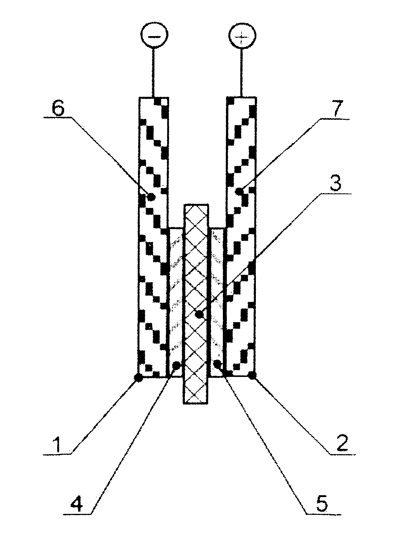
  • Electrochemical energy storage device of high specific power and electrodes for said device
  • Electrochemical energy storage device of high specific power and electrodes for said device
  • Electrochemical energy storage device of high specific power and electrodes for said device

Examples


example 1

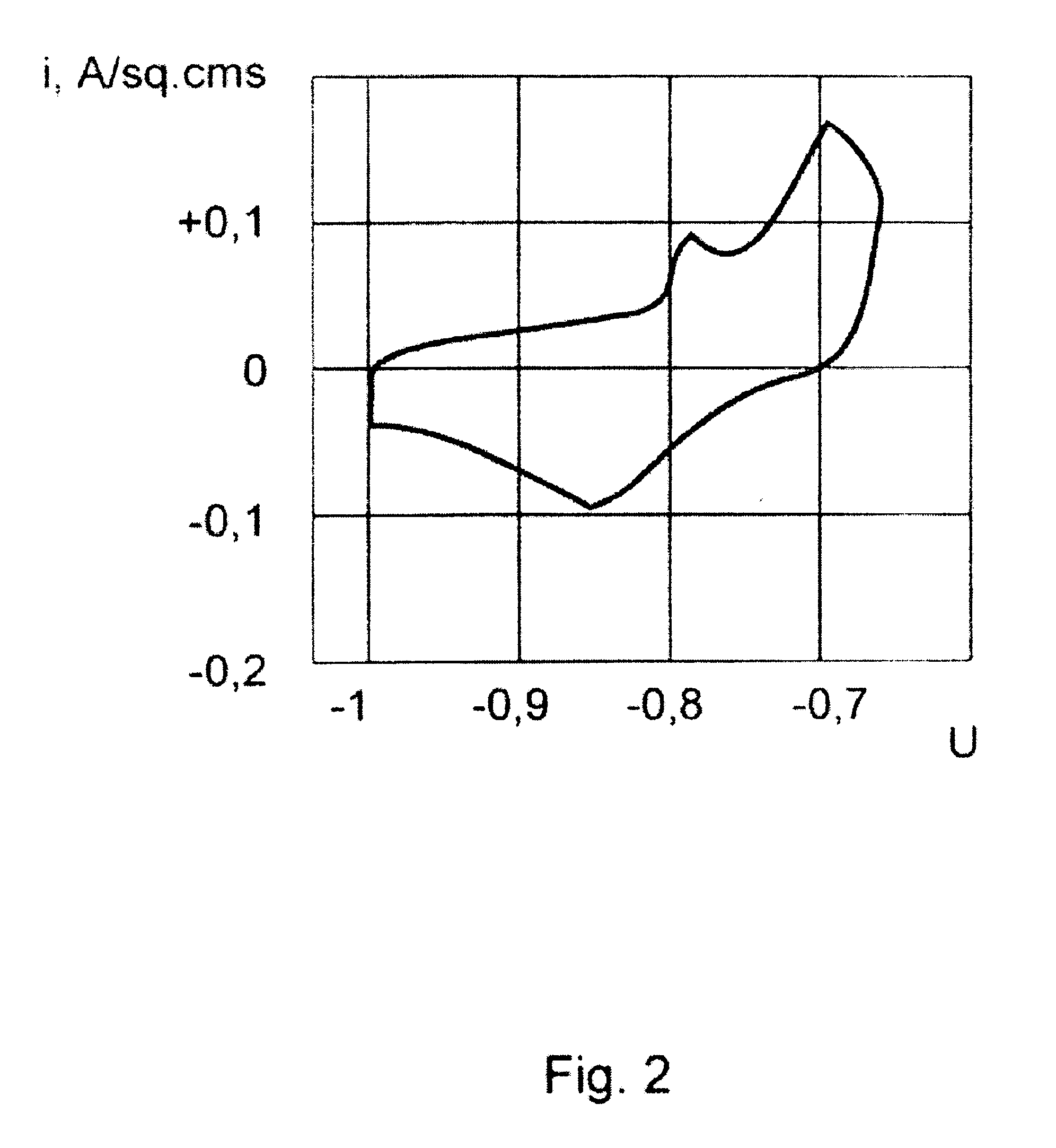
The negative electrode is obtained by electrochemical deposition (electrodeposition) of nickel on the backing made of rolled nickel foil 25 μm thick under conditions given in Table 1. The composition of the obtained electrolytic alloy (deposit)—Ni0.67O0.13H0.2—was defined by gas analysis of the deposit. Specific charge of the electrode was defined by discharge curves at galvanostatic discharge of the electrode in 30% KOH solution. Prior to discharge the electrode was held at the potential of minus 1.0 V against mercury oxide reference electrode during 5 minutes. Discharging with current density of 0.1 A / cm2 continued until attainment of potential of minus 0.6 V. The discharge curve was plotted by a high speed recorder. The specific charge was defined by multiplying the time of discharge in seconds by the current density 0.1 A / cm2. At deposit thickness of 25 μm (mass being 20 mg / cm2) specific charge of the electrode is 2.3 C / cm2 or 115 C / g. This value is five times higher than corres...

example 2

The negative electrode is obtained as in example 1 but in a different electrolyte and under different conditions of electrochemical deposition (see Table 1). Composition of the obtained electrolytic sediment is Ni0.63O0.15H0.22, mass is 17 mg / cm2, specific charge is 165 C / g which is higher than in example 1.

example 3

The negative electrode is obtained (see Table 1) by electrodeposition of nickel-cobalt alloy on polished titanium backing with following mechanical separation of the deposit from the backing (galvanoplastic method). Cobalt chloride was added to the electrolyte. Composition of the obtained electrolytic deposit is Ni0.52Co0.10O0.015H0.23, mass is 17 mg / cm2, specific charge is 170 C / cm2. The deposit separated from the backing is plastic and can be used as an electrode without any additional collector.


PUM


Abstract

The claimed invention relates to electrical engineering, and in particular to production of rechargeable electrochemical energy storage devices of high specific power. Positive and negative electrodes for electrochemical energy storage device of high specific power according to the invention comprise active element interacting with aqueous alkaline electrolyte in the process of redox charge-discharge reactions made of electron-conductive electrolytic alloy having composition M(l-x-y)OxHy, where M for positive electrode is nickel or nickel-based alloy, M for negative electrode—a metal out of the group: iron, nickel, cobalt or an alloy on the basis of a metal out of this group, x is atomic fraction of absorbed oxygen in the electrolytic alloy being within the limits of 0.01≦x≦0.4, for positive electrode preferably in the limits of 0.05≦x≦0.4, y is atomic fraction of absorbed hydrogen in the electrolytic alloy being within the limits of 0.01≦y≦0.4, for negative electrode preferably in the limits of 0.05≦y≦0.4, the said electrolytic alloy functioning simultaneously as current-carrying collector and as active material.Electrochemical energy storage devices of high specific power according to three embodiments of the invention comprise at least one negative and one positive electrodes submerged in aqueous alkaline electrolyte and divided by a separator—a layer of ion-conductive but non electron-conductive material.Enhancement of service life owing to increase in number of recharge cycles under conditions of elimination of ecological harmful cadmium is the technical result achieved by the invention.

Description

TECHNICAL FIELDThe claimed invention relates to electrical engineering, and in particular to production of rechargeable electrochemical energy storage devices (accumulators, electrochemical capacitors) of high specific power, designed for using them in various branches of engineering, such as automotive industry, electrical tools, communication equipment, special electrical transport (workshop battery-operated trucks, loaders, invalid wheeled vehicles), in toys etc.BACKGROUND OF THE INVENTIONIt is well known that for many technical applications it is necessary to have rechargeable power sources of high specific power (over 0.5 kW / kg) at a rather high specific energy (over 1 kJ / kg). Widespread accumulators of various types have high specific energy (100 kJ / kg and higher) but they are not able to provide high specific power, because they possess too high internal resistance (M. A. Fetcenco et al. In 16th International seminar and exhibit on primary and secondary batteries. Mar. 1-4, 1...

Claims


Application Information

Patent Timeline
IPC IPC(8): H01M4/52H01M4/32H01M4/66H01M10/24H01M4/04H01G9/04H01M4/02H01G9/00H01M4/24H01M10/34
CPCH01M4/04H01M4/0438H01M4/0461H01M4/049H01M4/242H01M4/52H01M10/345H01M4/32Y02E60/124H01M4/661H01M2004/027H01M2004/028Y02E60/10
Inventor MIRZOEV, RUSTAM AMINOVICHSTYROV, MIKHAIL IVANOVICHSTEPANOVA, NATALYA ILIINICHNAMAIOROV, ALEXANDR IVANOVICH
Owner MIRZOEV RUSTAM AMINOVICH
Learn More