Magnetic recording medium and magnetic recording apparatus

a recording medium and magnetic technology, applied in the field of magnetic recording mediums, can solve the problems of unsuitable for the mass production of information recording media, high cost, etc., and achieve the effects of excellent thermal stability, low medium noise level, and high resistance to thermal fluctuation and thermal demagnetization

Inactive Publication Date: 2005-01-25
HITACHT MAXELL LTD
View PDF21 Cites 39 Cited by
  • Summary
  • Abstract
  • Description
  • Claims
  • Application Information

AI Technical Summary

Benefits of technology

The magnetic recording apparatus as described above is based on the use of the magnetic recording medium according to the first aspect or the second aspect of the present invention. Therefore, the magnetic recording apparatus is highly resistant to the thermal fluctuation and the thermal demagnetization. Further, the magnetic recording apparatus is excellent in thermal stability. It is possible to reproduce, at a low medium noise level, the information recorded at a high density in the magnetic recording layer of the magnetic recording medium.
According to a fifth aspect of the present invention, there is provided a method for producing a magnetic material containing an ordered alloy, the method comprising forming the ordered alloy by means of a method selected from the group consisting of a gas phase method, a melting method, and a sintering method after allowing a component for constituting the ordered alloy to contain B or while allowing the component for constituting the ordered alloy to contain B. According to the production method as described above, it is possible to lower the temperature at which the component for constituting the ordered alloy is ordered. When the gas phase method is used, for example, B and the component for constituting the ordered alloy may be mutually vaporized so that B is contained in the component for constituting the ordered alloy on the substrate. Specifically, it is possible to use the CVD method, the vacuum vapor deposition method, the MBE method, the sputtering method, and the ion beam method. When the melting method is used, B and the component for constituting the ordered alloy may be mixed and melted, or B and the component for constituting the ordered alloy may be mixed with each other after being melted, followed by being cooled to obtain a desired shape and effect solidification. When the sintering method is used, for example, a predetermined amount of powder composed of the component for constituting the ordered alloy and a predetermined amount of powder composed of B may be mixed with each other, and they are compressed and formed into a desired shape, followed by being sintered at a predetermined temperature. The content of B to be contained in the component for constituting the ordered alloy is appropriately selectable depending on, for example, the type and the way of use of the magnetic material to be produced. For example, when the magnetic material is used for the magnetic layer of the magnetic recording medium, it is possible to make selection so that the content of B in the recording layer is 5 atomic % to 20 atomic %.

Problems solved by technology

However, the substrate such as the silicon substrate, which is formed of a high melting temperature material, is not suitable for the mass production of the information-recording media, because the cost is expensive.

Method used


Image

  • Magnetic recording medium and magnetic recording apparatus
  • Magnetic recording medium and magnetic recording apparatus
  • Magnetic recording medium and magnetic recording apparatus

Examples


example 1

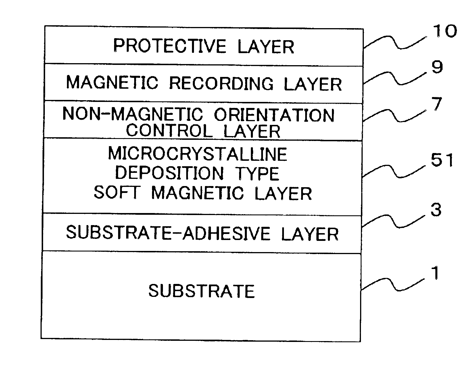
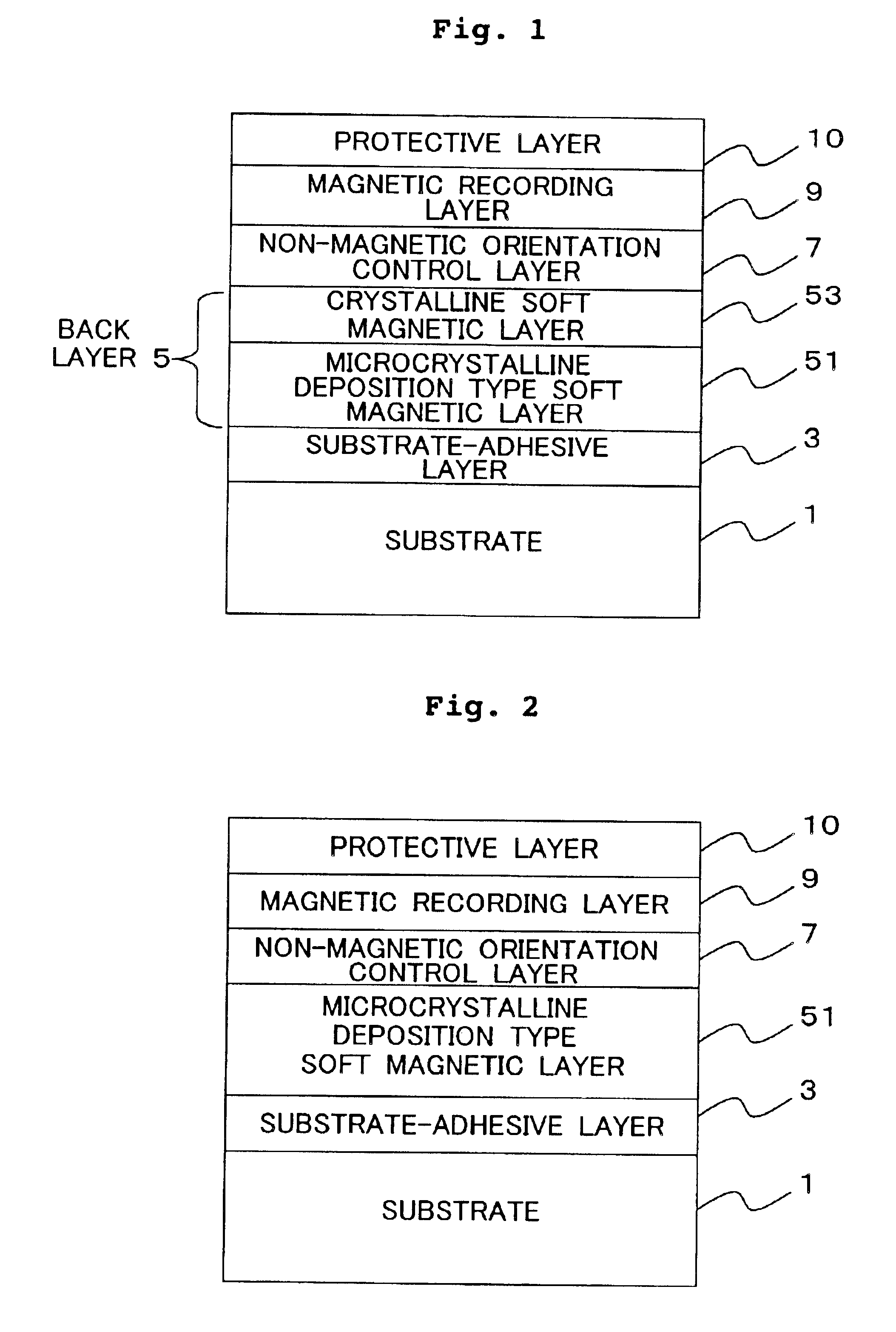
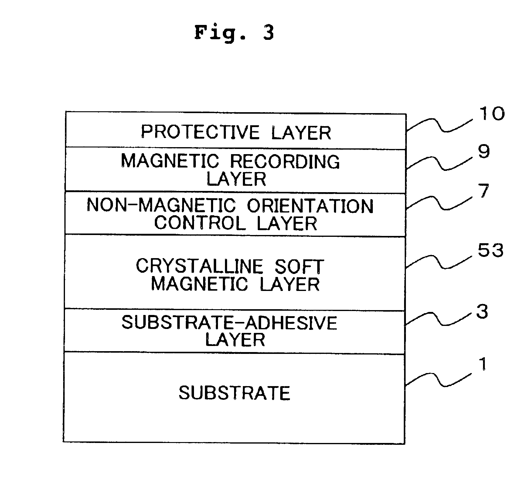
FIG. 1 shows a schematic sectional view illustrating a magnetic recording medium according to the present invention. The magnetic recording medium comprises, on a substrate 1, a substrate-adhesive layer 3, a back layer 5, a non-magnetic orientation control layer 7, a magnetic recording layer 9, and a protective layer 10. The back layer 5 is composed of a microcrystalline deposition type soft magnetic layer 51 and a crystalline soft magnetic layer 53. The crystalline soft magnetic layer 53 is formed on the side of the magnetic recording layer 9. In Example 1, Fe—Ta—C was used for the microcrystalline deposition type soft magnetic layer 51, and permalloy was used for the crystalline soft magnetic layer 53. However, there is no limitation thereto. A microcrystalline deposition type soft magnetic material such as Fe—Ta—N may be used for the microcrystalline deposition type soft magnetic layer 51 in place of Fe—Ta—C, and a crystalline soft magnetic material such as Fe—Al—Si may be used f...

example 2

FIG. 6 shows a schematic sectional view illustrating another specified embodiment of the magnetic recording medium according to the present invention. The magnetic recording medium comprises, on a substrate 1, a non-magnetic layer 62, a magnetic recording layer 63, and a protective layer 64. The magnetic recording medium was manufactured in accordance with the following procedure.

It is noted that in the following description, a glass substrate for the magnetic disk should be used in view of the industrial production, as the substrate of the medium to be used for the evaluation, in order to evaluate the characteristics of the manufactured medium. However, as described later on, an experiment was performed while applying the heat up to a high temperature at which it was difficult to use an ordinary glass substrate. Therefore, a thermally oxidized silicon substrate was firstly used to investigate the process for manufacturing the medium. After that, a glass substrate for the magnetic d...

example 3

FIG. 10 shows a schematic sectional view illustrating still another embodiment of the magnetic recording medium according to the present invention. The magnetic recording medium comprises a magnetic recording layer 9 and a protective layer 10 on a substrate 1. In Example 3, the magnetic recording layer 9 was formed directly on the substrate 1. However, in order to improve the crystalline orientation of the magnetic recording layer 9, a non-magnetic layer may be provided between the substrate 1 and the magnetic recording layer 9. Alternatively, a two-layered perpendicular magnetic recording medium may be constructed by providing a back layer which is formed of a soft magnetic material and which is disposed between the substrate 1 and the magnetic recording layer 9.

An explanation will be made below about a method for producing the magnetic recording medium having the laminated structure shown in FIG. 10.

At first, a washed quartz glass substrate for the magnetic disk was installed to a...


PUM

PropertyMeasurementUnit
average crystal grain diameteraaaaaaaaaa
temperatureaaaaaaaaaa
volume fractionaaaaaaaaaa

Abstract

A magnetic recording medium comprises a magnetic recording layer 63 which is formed by using an ordered alloy containing B on a substrate 1 containing an amorphous component. A part of B in the ordered alloy is segregated in a grain boundary, and thus the magnetic interaction, which acts between magnetic grains, can be reduced. Accordingly, it is possible to form fine and minute magnetic domains in the magnetic recording layer 63, and it is possible to reduce the medium noise as well. The temperature, at which the substrate is heated during the film formation of the magnetic recording layer 63, can be suppressed to be low, because the ordering temperature for the ordered alloy containing B is lower than those of ordered alloys not containing B. Therefore, it is possible to use a substrate made of glass which is suitable for the mass production. The magnetic recording layer 63 is also excellent in thermal stability because of the use of the ordered alloy having high magnetic anisotropy. According to the present invention, it is possible to provide the magnetic recording medium for high density recording which is excellent in thermal stability and which involves low medium noise.

Description

BACKGROUND OF THE INVENTION1. Field of the InventionThe present invention relates to a magnetic recording medium which is preferably used for the high density recording, a method for producing the same, and a magnetic recording apparatus. In particular, the present invention relates to a magnetic recording medium in which an ordered alloy is used for a magnetic recording layer, a method for producing the same, and a magnetic recording apparatus.2. Description of the Related ArtThose present in the field of the magnetic recording include two recording systems, i.e., the in-plane magnetic recording system and the perpendicular magnetic recording system. At present, the former recording system is generally used. The in-plane recording system is a method in which recording bits are formed by effecting the magnetization in parallel to the surface of a magnetic recording medium in a direction so that the N pole of the magnetic poles mutually abuts against the N pole and the S pole mutuall...

Claims


Application Information

Patent Timeline
Patent Type & Authority Patents(United States)
IPC IPC(8): G11B5/73G11B5/64G11B5/84G11B5/62G11B5/851H05K5/02G11B5/65G11B5/667H05K5/03H05K7/18H05K7/20
CPCG11B5/65G11B5/656G11B5/667G11B5/851G11B5/7325Y10T428/12854Y10S428/90Y10T428/12465G11B5/7368G11B5/737G11B5/7371G11B5/7373G11B5/7377G11B5/73921G11B5/62
Inventor INABA, NOBUYUKIKOUDA, TETSUNORIYAMANAKA, HIDEAKIMATSUNUMA, SATOSHIFUJITA, ENJI
Owner HITACHT MAXELL LTD
Why Eureka
Try Eureka