
Laser annealing apparatus and semiconductor device manufacturing method

a technology of laser annealing and semiconductor devices, which is applied in the direction of manufacturing tools, transportation and packaging, cranes, etc., can solve the problems of interference of reflected light from the surface of amorphous silicon films, and achieve the effect of reducing the formation of reflected light and low running cos

Inactive Publication Date: 2005-01-25
SEMICON ENERGY LAB CO LTD
View PDF24 Cites 24 Cited by
  • Summary
  • Abstract
  • Description
  • Claims
  • Application Information

AI Technical Summary

Benefits of technology

It is, therefore, an object of the present invention to provide a laser annealing method for a laser irradiation device which requires low running cost, capable of preventing the generation of a concentric pattern or decreasing the formation thereof and to provide a semiconductor device manufacturing method including a step using the laser annealing method.
The solid-state laser employed in the present invention can basically output a laser beam if a resonant mirror or a light source for exciting solid-state crystal is provided. Due to this, compared with the excimer laser, it does not take much labor for maintenance. That is, since the solid-state laser is far lower in running cost than the excimer laser, it is possible to greatly reduce semiconductor device manufacturing cost. In addition, if the frequency of the maintenance decreases, the operativity of a mass-production line improves and the overall throughput of the manufacturing process improves, which also greatly contributes to the reduction of the semiconductor device manufacturing cost. Besides, the area occupied by the solid-state laser is smaller than that of the excimer laser, it is advantageously effective for the design of a manufacturing line.

Problems solved by technology

It is considered that reflected light from the surface of the amorphous silicon film interferes with the laser beam transmitted by the amorphous silicon film on a certain surface.

Method used


Image

  • Laser annealing apparatus and semiconductor device manufacturing method
  • Laser annealing apparatus and semiconductor device manufacturing method
  • Laser annealing apparatus and semiconductor device manufacturing method

Examples


embodiment 1

An optical system will be described below with reference to FIG. 6 in this embodiment.

As a laser oscillator 201, it is desirable to use a high-power laser (a YAG laser, a YVO4 laser or the like). Of course, a gas laser, a glass laser or the like may also be used as long as it has high power. The laser light generated from the laser oscillator 201 is formed into a linear beam whose irradiation plane has a linear shape, by using the optical system. The optical system uses, for example, a long focal length cylindrical lens 205 for enlarging a laser beam into a long beam, and a cylindrical lens 206 for converging a laser beam into a thin beam. By using such long focal length cylindrical lenses, it is possible to obtain a laser beam which is reduced in aberration and is uniform in energy distribution at or near the irradiation plane. In addition, the long focal length cylindrical lenses are effective in restraining a remarkable difference from occurring between the beam width of a beam i...

embodiment 2

This embodiment describes the method of crystalline for the laser anneal device.

First, a glass substrate (Corning 1737 with a glass distortion temperature of 667° C.) was prepared as a substrate 1000. Then, a protective film 1001 is formed on the substrate 1000, and a tantalum nitride film 1002a (50 nm thick) and tantalum film 1002a (250 nm thick) were formed successively in the form of a multilayer configuration on the protective film 1000 by sputtering. (FIG. 7A) Then, the gate electrode 1002 having a multi layer configuration formed by photolisography, which is conventional patterning method.

Subsequently, the gate insulating film and the amorphous semiconductor film 1004 were formed successively in the form of a multilayer configuration without being exposed to the atmosphere (FIG. 7C). In this embodiment, in order to prevent impurities from diffusing from the gate wiring to the semiconductor film and the gate insulating film during fabrication, the silicon nitride film 1003a (50...

embodiment 3

The structure of the active matrix liquid crystal display device obtained by using Embodiment1 and 2 will be described with reference to the top view of FIG. 8 to 9.

In the top view of active matrix display device shown in FIG. 8A, the pixel portion 811, the driver circuit (general name of gate driving circuit 805 and source driving circuit 807), an external input terminal 803 to which an FPC (Flexible Printed Circuit) is bonded, a wiring 804 for connecting the external input terminal 803 with input sections of the respective circuits, and the like are formed on an active matrix substrate 801. The active matrix substrate 801 and an opposing substrate 802, on which a color filter and the like are formed, are bonded with each other, sandwiching an end-sealing material 809 therebetween.

A gate driving circuit has the function to input the signal to selected gate wiring 806. The gate wiring 806 is the wiring that connects to gate electrode electrically. And the selected gate wirings are s...


PUM

PropertyMeasurementUnit
angleaaaaaaaaaa
poweraaaaaaaaaa
lengthaaaaaaaaaa

Abstract

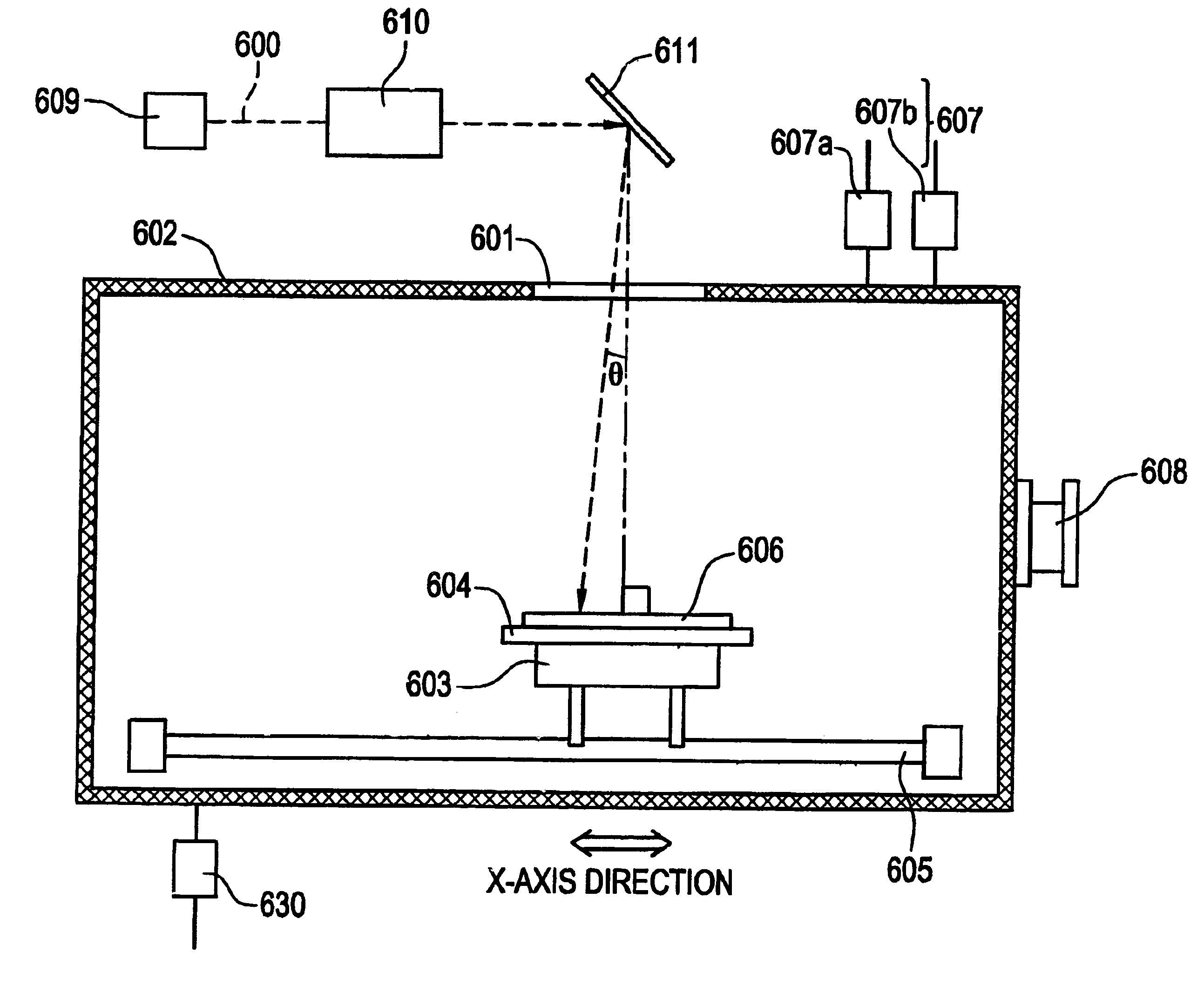
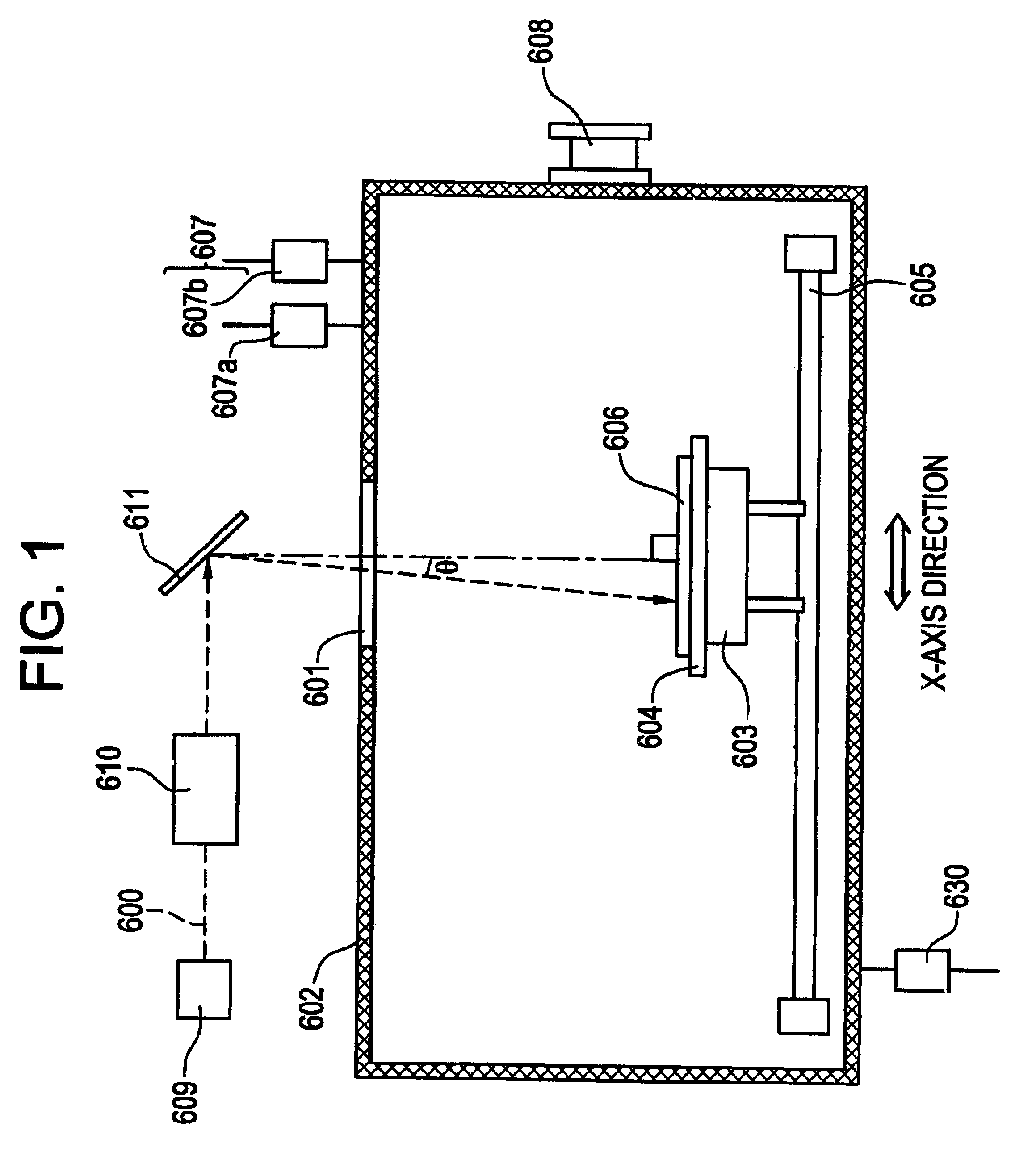
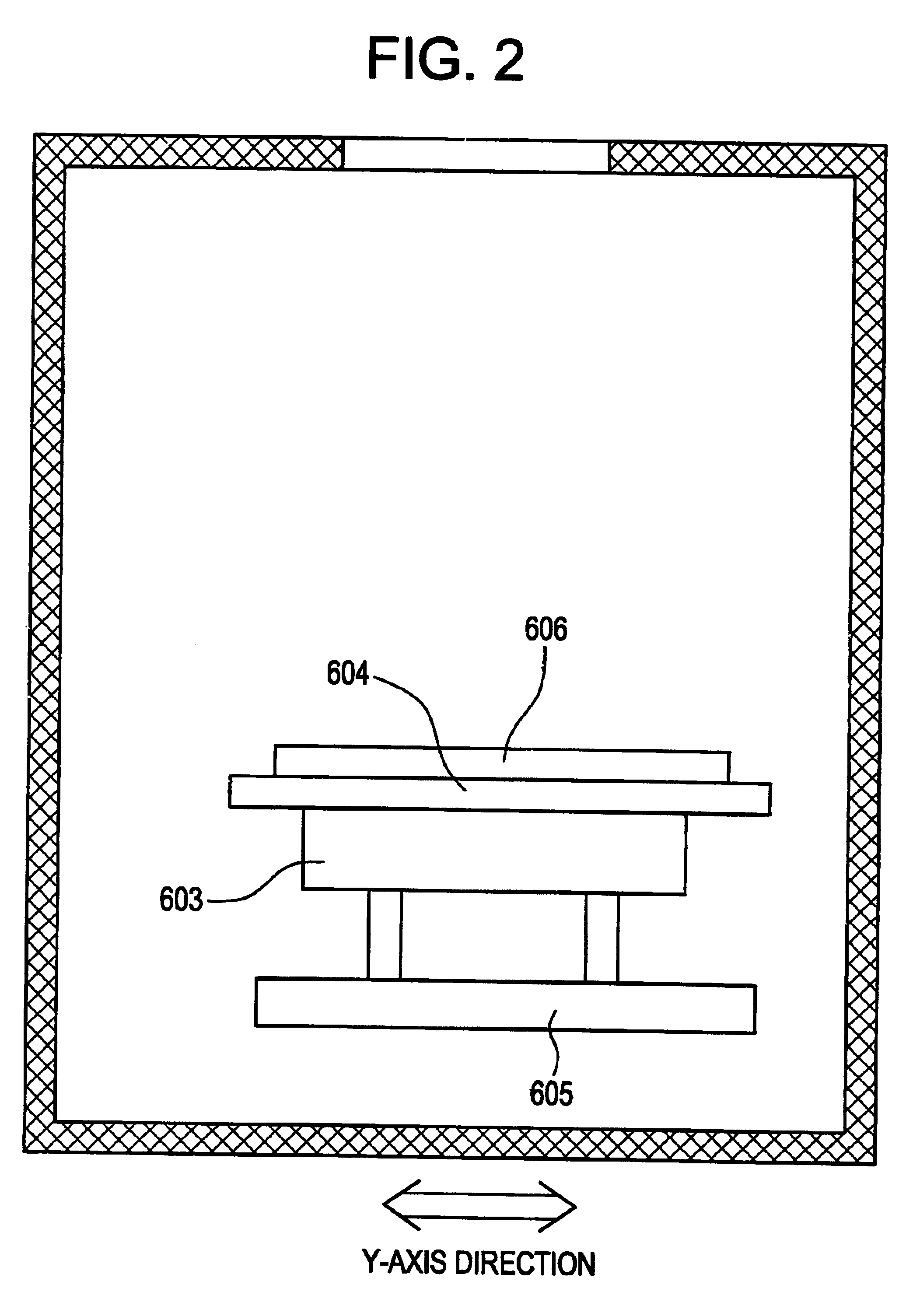
This invention is intended to provide a laser annealing method by employing a laser annealer lower in running cost so as to deal with a large-sized substrate, for preventing or decreasing the generation of a concentric pattern and to provide a semiconductor device manufacturing method including a step using the laser annealing method. While moving a substrate at a constant rate between 20 and 200 cm / s, a laser beam is radiated aslant to a semiconductor film on a surface of the semiconductor substrate. Therefore, it is possible to radiate a uniform laser beam to even a semiconductor film on a large-sized substrate and to thereby manufacture a semiconductor device for which the generation of a concentric pattern is prevented or decreased. By condensing a plurality of laser beams into one flux, it is possible to prevent or decrease the generation of a concentric pattern and to thereby improve the reliability of the semiconductor device.

Description

BACKGROUND OF THE INVENTION1. Field of the InventionThe present invention relates to a laser annealer employing a laser beam. The present invention also relates to a semiconductor device manufacturing method for manufacturing a semiconductor device through steps including a step using a laser annealing method. The semiconductor device means herein one of a general device which can function by employing semiconductor characteristic and which involve an electro-optic device such as a liquid crystal display and a light emitting device, and an electronic device which has the electro-optic device incorporated therein as a component.In recent years, study has been broadly made on the art to carry out laser anneal on a semiconductor film formed over an insulating substrate of glass or the like in order for crystallization or improving crystallinity. Such semiconductor films often use silicon. In the present description, the means for crystallizing a semiconductor film by using a laser beam...

Claims


Application Information

Patent Timeline
Patent Type & Authority Patents(United States)
IPC IPC(8): B23K26/08C21D1/34H01L21/268H01L21/20H01L21/314
CPCB23K26/0838H01L21/2026C21D1/34H01L21/02686H01L21/02683H01L21/02678H01L21/02422H01L21/02491H01L21/02488H01L21/02532H01L21/02505H01L21/0242H01L21/02381H01L21/02691H01L21/268
Inventor YAMAZAKI, SHUNPEITANAKA, KOICHIROHIROKI, MASAAKI
Owner SEMICON ENERGY LAB CO LTD
Learn More