Adhesiveless microfluidic device fabrication

a technology of microfluidic devices and adhesives, which is applied in the direction of electrolysis, diaphragms, chemical vapor deposition coatings, etc., can solve the problems of complex biochemical reactions and processes, unfavorable application in other applications, and the ability of adhesives to be susceptible to undesirable interactions with certain chemical solvents, etc., to enhance the fabrication method and high inter-layer bond strength

Inactive Publication Date: 2005-02-01
AGILENT TECH INC
View PDF58 Cites 78 Cited by
  • Summary
  • Abstract
  • Description
  • Claims
  • Application Information

AI Technical Summary

Benefits of technology

In a first separate aspect of the invention, a method for fabricating a microfluidic device several method steps. A first method step includes providing a first and a second substantially flat platen. A second method step includes providing multiple substantially planar, substantially metal-free, adhesiveless polymer device layers, the device layers including a first cover layer, second cover layer, and at least one stencil layer defining a microfluidic channel penetrating through the entire thickness of the stencil layer. Each stencil layer is disposed between other device layers such that the channel is bounded laterally by a stencil layer, and bounded from above and below by s

Problems solved by technology

In particular, when conducted in microfluidic volumes, complicated biochemical reactions and processes may be carried out using very small volumes of fluid.
Furthermore, when conducted in microfluidic volumes, a large number of complicated biochemical reactions and/or processes may be carried out in a small area, such as in a single integrated device.
While microfluidic devices fabricated with adhesives may be suitable for certain applications, their extension in other applications would be problematic.
For example, adhesives may be susceptible to undesirable interaction with certain chemical solvents, particularly organic solvents.
Undesirable interaction between such solvents and adhesives may vary in scope from relatively benign chemical reaction to more serious dissolution or chemical breakdown, leading to observable effects ranging from skewed detection results to structural failure of devices.
Aside from these chemical interaction effects, adhesives in microfluidic devices may also interfere with biological reactions, such as, for example, non-specific binding studies.
Another potential limitation of adhesives—particularly pressure-sensitive adhesives—in fluidic devices is that adhesives are characterized by limited bond strength, which in turn limits the range of fluid pressures with which such devices may be operated.
Typical pressure-sensitive adhesives are unsuitable for use in fluidic devices intended to handle pressures greater than approximately 100 psi (689.5 kPa).
Although methods have been developed for fabricating microfluidic devices in selected materials without using adhesives, such methods are not without other drawbacks.
The presence of metal ions limits the utility of such devices in several applications.
In one desirable microfluidic application, chromatography, the presence of metal ions would be detrimental for several reasons.
For example, metal ions can contaminate stationary phase material, thus rendering the stationary phase material incapable of performing its in

Method used


Image

  • Adhesiveless microfluidic device fabrication
  • Adhesiveless microfluidic device fabrication
  • Adhesiveless microfluidic device fabrication

Examples


example 1

Several copies of a square adhesiveless microfluidic channel-containing device were constructed with three device layers 51-53, with edge lengths of about 2.5 inches (6.4 cm). Referring to FIGS. 3A-3B, in each device the first (cover) layer 51 defined an inlet port 55 and an outlet port 56 for each channel 57. Eight channels 57, each 40 mils (1 mm) wide, were cut into and through the entire thickness of the central stencil layer 52. The third (cover) layer 53 served to enclose the channels 57 from the bottom. Each layer 51-53 defined two alignment holes 58, 59 to aid in aligning the layers 51-53 when stacking atop an alignment jig with raised pegs (not shown). The three layers 51-53 were each formed of 7.5 mil (188 micron) thickness unoriented “Clear Tear-Seal” polypropylene (American Profol, Cedar Rapids, Iowa) and stacked together. No adhesives or metallic bonding agents were used.

In one batch, the channels 57 were cut with a computer-controlled laser cutter. Multiple (i.e., four)...

example 2

Another batch of devices 50 identical in appearance to those described in Example 1 was prepared. The only difference in preparing the device layers 51-53 before stacking was that the channels 57 were cut using a plotter that was modified to manipulate a cutting blade. Nine aligned identical stacks of layers 51-53 were prepared and tack-welded at two locations each using a laser to provide a localized weak bond between layers. This welding step locally heated the material to approximately its melting point but did not burn or remove any material. This localized welding was performed to prevent slippage between layers 51-53 when placed within a compression jig.

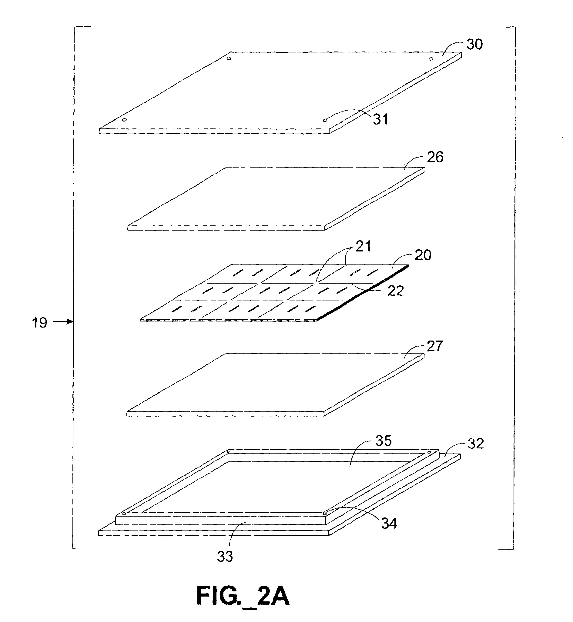
The nine stacks were placed symmetrically, in three rows of three stacks each, between glass platens in a compression jig according to FIGS. 2A-2D. In this example, the compression springs 38 were each approximately ⅝ inch (16 mm) in length, 0.24 inch (6.1 mm) in diameter, and had a spring rate of about 28 pounds / inch (5.0 kg / c...

example 3

Multiple copies of a microfluidic channel-containing device were constructed using five device layers 71-75. As shown in FIGS. 4A-4B, three stencil layers 72-74 were sandwiched between a first and a second cover layer 71, 75. The first layer 71 defined multiple inlet and outlet ports 77, 78. Eight channels 80, each approximately 40 mils (1 mm) wide were cut into and through the entire thickness of the second (stencil) layer 72, along with vias 81 and 82 for communicating with channels 84, 88 in the third and fourth layers 73, 74. The third layer 84 and the fourth layer 88 were stencil layers each defining eight channels 84, 88, with the third layer additionally defining vias 85, 86 for communicating with the channels 88. The channels 80, 84, 88 were all slightly offset from one another, as clearly depicted in FIG. 4B. The fifth layer 75 served as a base for sealing the channels 88 defined in the fourth layer 74. All five layers 71-75 were formed of 7.5 mil (188 micron) thickness uno...


PUM

PropertyMeasurementUnit
Fractionaaaaaaaaaa
Fractionaaaaaaaaaa
Fractionaaaaaaaaaa

Abstract

A method for fabricating a microfluidic device where first and second substantially flat platens are provided. Multiple substantially planar, substantially metal-free, adhesiveless polymer device layers, the device layers including a first cover layer, second cover layer, and at least one stencil layer defining a microfluidic channel penetrating through the entire thickness of the stencil layer also are provided. Each stencil layer is disposed between other device layers such that the channel is bounded laterally by a stencil layer, and bounded from above and below by surrounding device layers to define an upper channel surface and a lower channel surface. The device layers are stacked between the first platen and the second platen. The stacked device layers are controllably heated according to a heating profile adapted to form a substantially sealed adhesiveless microfluidic device wherein each upper channel surface remains distinct from its corresponding lower channel surface. The resulting microfluidic device has high inter-layer bond strength while preserving the integrity of the channel(s) defined in the stencil layer(s).

Description

FIELD OF THE INVENTIONThe present invention relates to the manufacture of microfluidic structures, i.e., structures for handling microscopic volumes of fluid.BACKGROUND OF THE INVENTIONThere has been a growing interest in the application of microfluidic systems to a variety of technical areas. For example, use of microfluidic systems for the acquisition of chemical and biological information presents certain advantages. In particular, when conducted in microfluidic volumes, complicated biochemical reactions and processes may be carried out using very small volumes of fluid. In addition to minimizing sample volume, microfluidic systems improve the response time of reactions and reduce reagent consumption. Furthermore, when conducted in microfluidic volumes, a large number of complicated biochemical reactions and / or processes may be carried out in a small area, such as in a single integrated device. Examples of desirable applications for microfluidic technology include analytical chem...

Claims


Application Information

Patent Timeline
IPC IPC(8): B01L3/00B29C65/00B29C65/18G01N27/447B32B37/08B81C1/00
CPCB01L3/502707B01L3/502738B29C65/18B29C66/02B29C66/45B32B37/0023B32B37/10B32B38/004B81C1/00119B81C3/008G01N27/44791B29C66/929B29C66/92445B29C66/961B29C66/91411B29C66/91445B29C66/91645B29C66/91212B29C66/91231B01J2219/00783B29C66/727B01J2219/00835B01J2219/00891B01J2219/00952B01L3/502746B01L2200/0689B01L2200/10B01L2200/12B01L2300/0681B01L2300/0874B01L2300/0887B01L2300/14B29C66/026B29K2023/00B29K2023/12B29L2031/756B32B37/08B32B2037/0092B32B2038/166B32B2309/02B32B2309/022B32B2309/12B32B2310/024B81B2201/058B81C2201/019G01N30/6095B01J2219/00833Y10T29/49002B29C66/91213B32B41/00B29C66/91216B29C66/91221B29C2035/0827B29C66/9241B29C65/00B29C66/1122B29C66/71B29C66/73112B29C66/8322Y10T137/0402Y10T137/2224Y10T137/598B29K2067/00
Inventor COVINGTON, JOSEPH F.HOBBS, STEVEN E.KOEHLER, JEFFREY A.PATEL, PAREN P.PEZZUTO, MARCISCHEIB, MARK S.
Owner AGILENT TECH INC
Why Eureka
Try Eureka