Embossed current collector separator for electrochemical fuel cell

a fuel cell and collector separator technology, applied in the field of bipolar current collector separator for fuel cells, can solve the problems of poor mechanical strength and high machining cost, difficult to utilize the conventional graphite separators as separators for on-vehicle fuel cells, and low mechanical strength and machining cos

Inactive Publication Date: 2005-02-08
RIKEN CO LTD
View PDF5 Cites 11 Cited by
  • Summary
  • Abstract
  • Description
  • Claims
  • Application Information

AI Technical Summary

Benefits of technology

An object of the present invention is to provide a metal bipolar current collector separator for a fuel cell excellent in corrosion resistance.
As a result of intense research in view of the above object, the inventors have found that corrosion resistance of a metal bipolar current collector separator for a fuel cell can be improved by disposing a corrosion-resistant layer on a small part thereof. The present invention has been accomplished by the finding.

Problems solved by technology

Although the graphite separators are low in electric resistance and high in corrosion resistance, they are poor in mechanical strength and high in machining cost.
Thus, it is difficult to utilize the conventional graphite separators as the separator for the on-vehicle fuel cells, which is required to be high in the mechanical strength and low in the machining cost.
Recently proposed is a separator that is produced by mixing graphite powder with a resin, and by injection-molding and baking the resulting mixture, however, there is a problem that it is low in density to be poor in the air-tightness.
Although the density can be increased by impregnating the separator with a resin and by burning the resultant again to carbonize it, this results in complicated manufacturing processes.
However, there is a problem that the metal material is liable to corrode, in particular, it has been known that aluminum exhibits extremely high corrosion rate (R. L. Rorup et al., Mater. Res. Soc. Symp. Proc., 393 (1995), etc.).
Further, there is a fear that metal ions generated by corrosion of the metal material penetrate into the electrolyte membrane to reduce the ion-conductivity thereof.
Although this metal separator plated with a noble metal sufficiently acts as a separator, it necessitates high production cost to be far from practicable.
However, when a thinner noble metal layer is disposed by wet plating methods, the resultant layer has fine pinholes that cause corrosion of the metal separator.
On the other hand, dry plating methods such as vapor deposition methods and sputtering methods are poor in efficiency of producing the thinner noble metal layer, and the resultant layer is poor in uniformity.

Method used


Image

  • Embossed current collector separator for electrochemical fuel cell
  • Embossed current collector separator for electrochemical fuel cell
  • Embossed current collector separator for electrochemical fuel cell

Examples


example 1

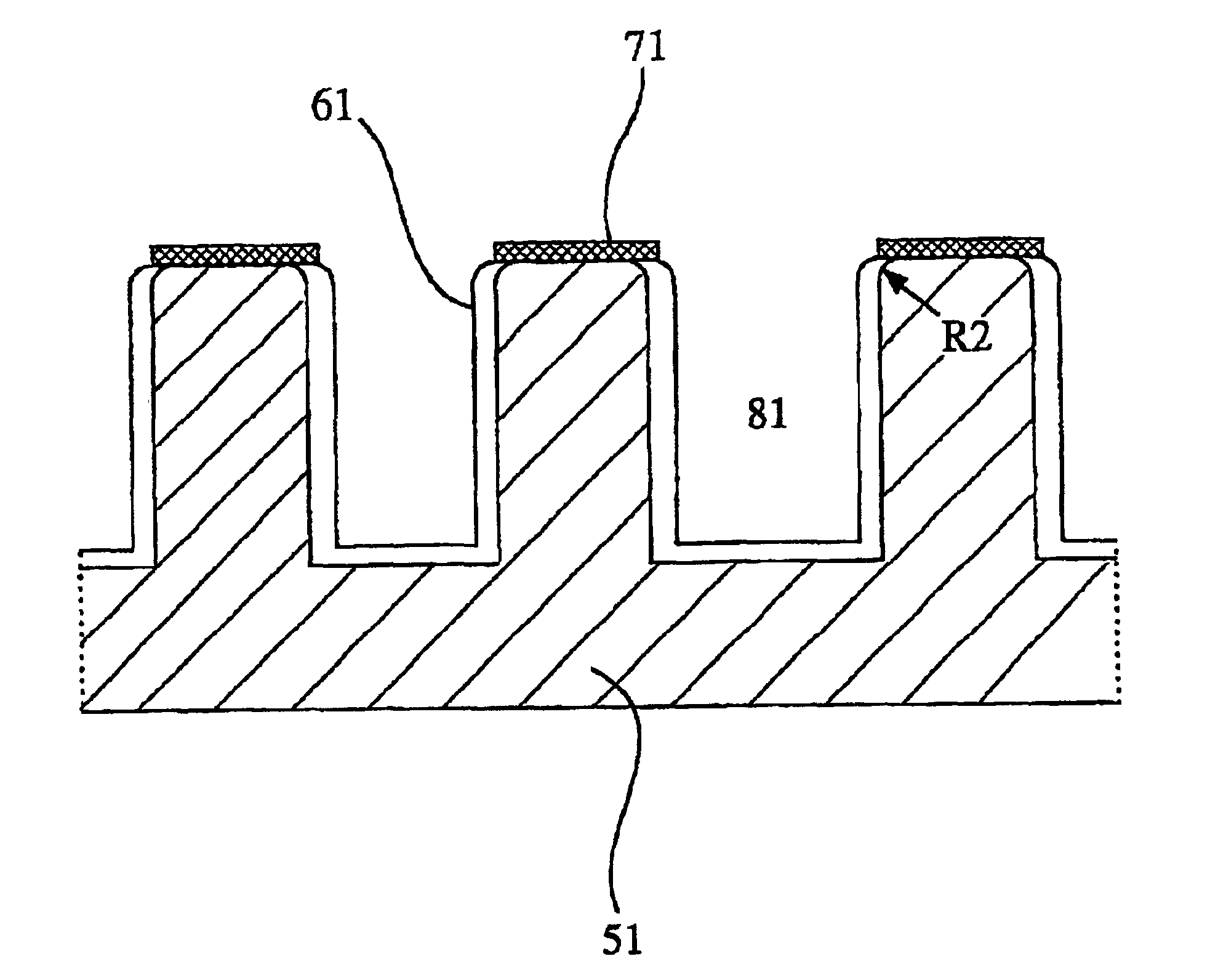
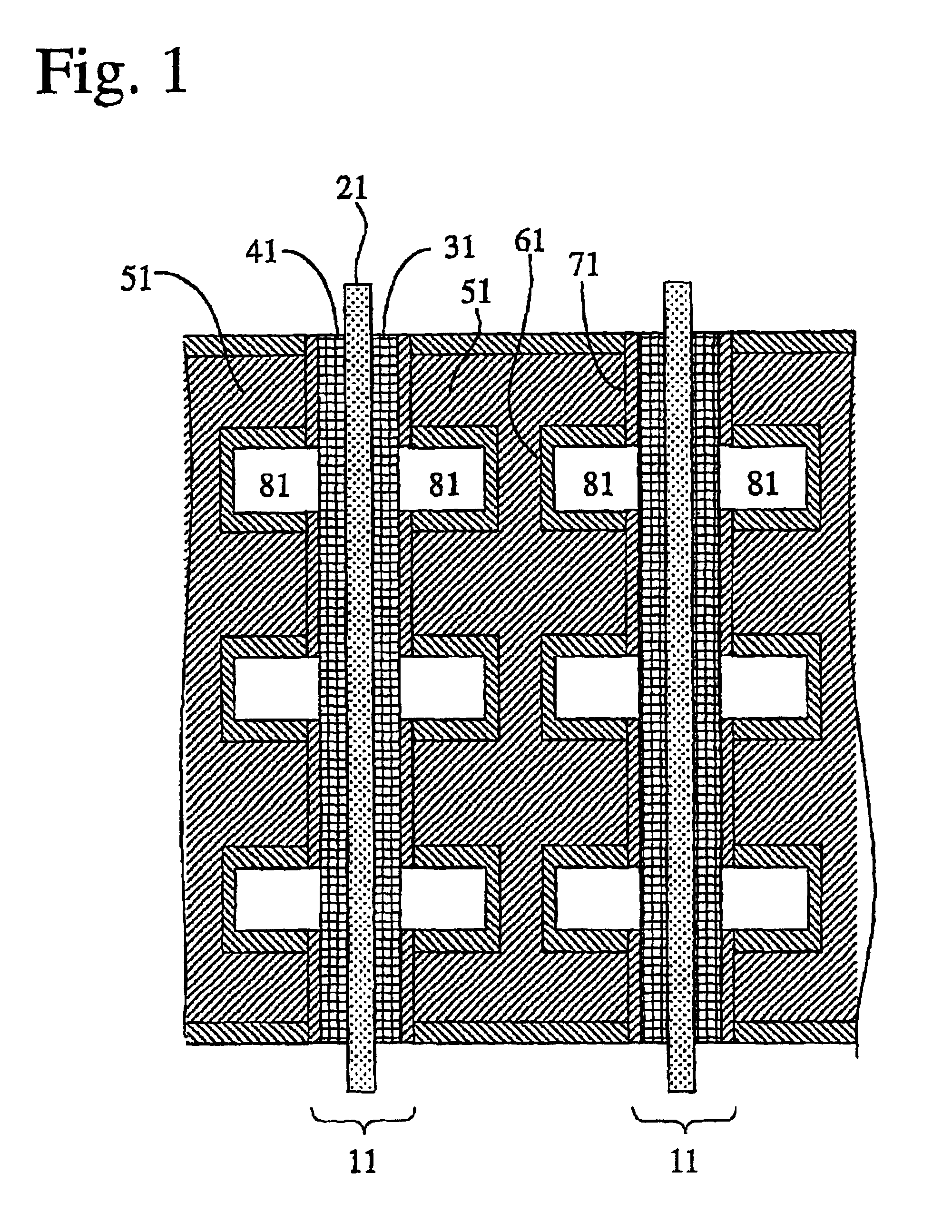
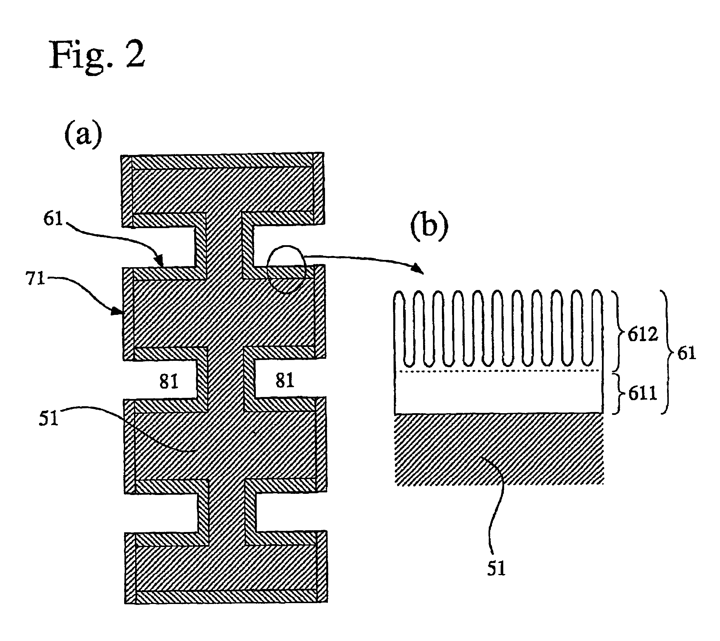
An aluminum metal plate of 1 mm×150 mm×150 mm in size having a purity of 99.6% was press-worked to form flow channels having a depth of 1.0 mm and a width of 3.0 mm thereon, so that a separator base was prepared. This separator base was anodized in an oxalic acid aqueous solution, immersed in boiling water for 30 minutes, and dried to dispose an anodized aluminum layer having a thickness of 12 μm thereon. Then, electrode contact faces of the anodized separator base were lapped and washed, to improve the flatness thereof and remove the anodized aluminum layer thereon. Subsequently, each of the electrode contact faces was sputtered with Au at a separator base temperature of 200° C. under pure argon gas of 5 mTorr to dispose a conductive film having a thickness of approximately 1 μm, so that a separator was produced.

To 100 parts by weight of carbon black was added 15 parts by weight of a Pt paste (Pt-content: 90 weight %), and to this was further added 15 parts by weight of Teflon part...

example 2

Fuel cells 2a to 2s using the first separators of the present invention were produced in the same manner as the above-mentioned fuel cell 1a except for using materials shown in Table 2 instead of Au for the conductive film, respectively. Here, the conductive films of the fuel cells 2q and 2r were each disposed by sputtering carbon (fuel cell 2q) or conductive carbide SiC (fuel cell 2r) to the electrode contact faces under argon gas of 30 mTorr while using a target thereof.

To each of the fuel cells 2a to 2s using the first separators of the present invention and above-mentioned comparative fuel cell 1b was supplied a humidified, simulated fuel gas containing 70 volume % of H2, 20 volume % of CO2 and 10 volume % of H2O through the flow channels on the anode side, and supplied air as an oxidizing agent through the flow channels on the cathode side, so that each of the fuel cells 2a to 2s and 1b was evaluated with respect to the stability of electric generation. Material used for conduc...

example 3

Fuel cells 3a to 3j using the first separators of the present invention were produced in the same manner as the above-mentioned fuel cell 1a except that the porosity of the anodized aluminum layer was changed as shown in Table 3 by controlling conditions for disposing the anodized aluminum layer, respectively. Each of the fuel cells 3a to 3j was evaluated with respect to the stability of electric generation in the same manner as Example 2. Porosity of anodized aluminum layer, initial electric generation voltage, electric generation voltage after working for 10 days, and condition of separator after working for 10 days of each fuel cell were shown in Table 3.

TABLE 3ElectricConditiongenerationofPorosity ofInitialvoltage afterseparatoranodizedelectricworkingafterFuelaluminumgenerationfor 10 daysworkingcelllayer (%)voltage (V)(V)for 10 days3a0.860.810.83a*3b1.250.820.81a*3c1.630.860.84a*3d2.010.830.81a*3e2.670.790.75b*3f3.020.840.78b*3g3.540.850.75b*3h5.060.880.73b*3i7.320.810.63c*3j10....


PUM

PropertyMeasurementUnit
porosityaaaaaaaaaa
thicknessaaaaaaaaaa
curvature radiusaaaaaaaaaa

Abstract

A bipolar current collector separator for a fuel cell composed of a metal plate having flow channels and contact faces that come into contact with electrodes or collectors, wherein a corrosion-resistant layer such as an anodized aluminum layer and a heat-resistant polymer layer is disposed on each of the flow channels.

Description

BACKGROUND OF THE INVENTIONThe present invention relates to a bipolar current collector separator for a fuel cell, particularly to a separator applicable to an on-vehicle fuel cell for an automobile.Fuel cells have attracted much attention as next generation electric generators because they are excellent in energy conversion efficiency and discharge no harmful or toxic substances. In particular, fuel cells using a solid polymer electrolyte membrane (hereinafter referred to as “PEM”) that work at 150° C. or less have been studied actively and expected to be made practicable a few years later. The fuel cells using PEM can work at a relatively low temperature, be high in output density of electric generation, and be miniaturized, thereby suitable for domestic or on-vehicle fuel cells.In general, the fuel cell using the PEM is produced by disposing the PEM between a fuel electrode and an oxygen / air electrode to prepare a cell, and by stacking a plurality of the cells with each other thr...

Claims


Application Information

Patent Timeline
Patent Type & Authority Patents(United States)
IPC IPC(8): H01M8/02
CPCH01M8/0206H01M8/0221H01M8/0232H01M8/026H01M8/0228Y02E60/50
Inventor GAO, YUNZHIKUNIMOTO, AKIRA
Owner RIKEN CO LTD
Why Eureka
Try Eureka