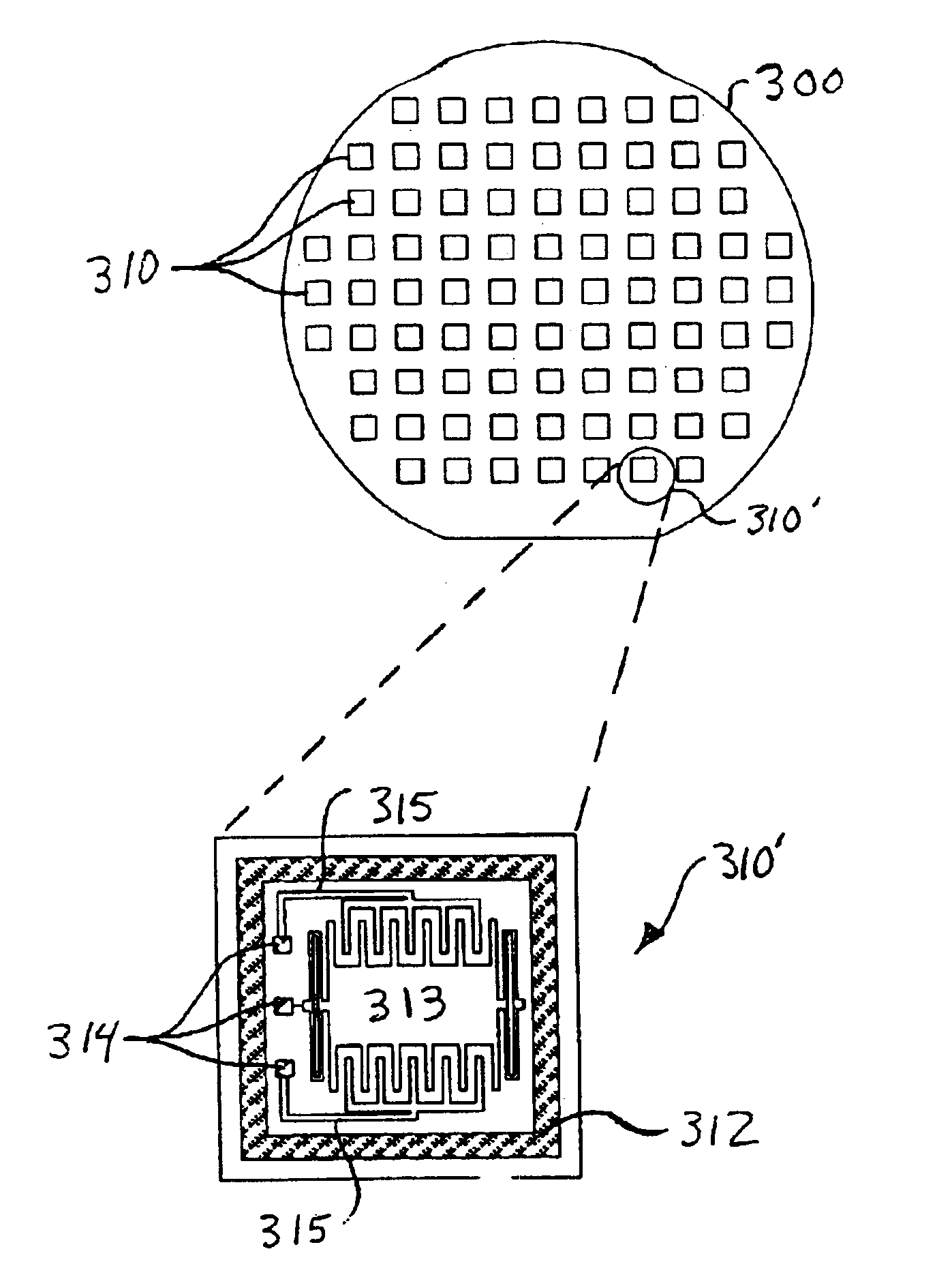
Although they are generally fabricated on
silicon wafers, these “microelectromechanical devices” or “MEMS” are different from most ICs in that they possess moving elements.
Although MEMS devices are even more vulnerable to
contamination and
moisture than most ICs, they cannot be encapsulated in a typical injection-molded plastic
package because at least one element of every microelectromechanical device must remain free to move.
The packaging of MEMS devices, therefore, presents unique problems.
One problem with this
chip-scale packaging approach is the expense associated with handling the individual components (e.g., the packages, lids, etc.) and assembling them into a single
package.
An additional problem with this
chip-scale packaging approach is that the moving elements in MEMS are extremely fragile and tend to be damaged by any handling, especially near the end of the fabrication process.
Therefore, packaging yields are typically low.
A further problem with this packaging approach is that the solder seal on the lid tends to outgas when reflowed during the final sealing process.
If a vacuum is needed inside the package, a
getter must be added, at additional cost.
In such cases, packaging costs can constitute 80% of the total device cost.
In sum, the use of
ceramic packages to seal and package MEMS chips is inordinately expensive due to the need to individually
handle components, the need to use getters and the considerable opportunity for damage and
contamination of the MEMS devices.
While this process has been marginally successful, it suffers from the deficiency that the glass
frit cannot be patterned into fine features.
Attempts have been made to improve the glass
frit patterning resolution, using lithographic methods, but these have not shown success.
Further,
gasket patterns thinner than 100-200 microns in width do not appear to provide reliable hermetic seals, possibly because of the inherently porous nature of glass frits.
Thus, it is currently believed that glass
frit techniques simply cannot be applied on a smaller scale where hermetic seals are desired.
One drawback of using such a high firing temperatures is that it effectively precludes the incorporation of integrated circuitry on either of the wafers bonded together.
Such high temperatures also damage the MEMS themselves and, particularly, certain structural films deposited at lower temperatures and structures in which the film stress must be carefully controlled.
Another deficiency of glass frit techniques is that the glass frit itself employs organic binders, which outgas into the sealed cavity during firing.
Since getters are not available to combat this problem, this fact precludes the use of glass frits for vacuum applications.
Still another limitation of the glass frit techniques is that the sealing materials, being non-conductive, cannot be used to establish electrical
coupling between the devices disposed on the bonded substrates.
These methods also place strict constraints on the materials and processes used to form the wafers to be bonded together.
Significantly, these methods are also exceptionally sensitive to the presence of even small particulate contaminants,
wafer warpage, scratches, and other imperfections commonly encountered during
semiconductor fabrication because such contaminants can cause large defects in the bond and reduce yield substantially.
Moreover, normal variations in surface topology due to the presence of circuitry can preclude proper bonding and / or sealing using such methods.
The use of solder to form a seal is not compatible with present MEMS process technologies because MEMS are easily damaged by residual solder flux left after sealing has occurred.
While fluxless
soldering processes have been attempted, even this approach does not resolve an inherent real-estate inefficiency problem resulting from the fact that the minimum feature size of this solder-based technology is about 100 microns.
Yet another problem with solder-based flip-
chip bonding is that special
processing is required; not only for fabrication of the solder structures on the lid chip, but also to coat the appropriate areas of the microsensor chip with a solderable
metal.
Since some standard metals used by commercial IC foundries cannot be soldered directly, solder-based flip-chip technology is still expensive and of limited utility compared to the present invention.
Finally, solder-based flip-chip bonding cannot be reliably performed on a
wafer-scale because, for example, the normal curvature of processed wafers can exceed the solder bump height.
For all of the reasons above, this chip-scale technique is disproportionately expensive relative to wafer-scale packaging / sealing techniques.
Possibly, this is because manufacturers have confined themselves to standard packaging techniques, such as wirebonding, flip-chip, etc.
Therefore, many manufacturers would be unlikely to use gold in their MEMS products.

