Photoresist composition

a composition and photoresist technology, applied in the field of photoresists, can solve the problems of increasing the functional capacity of photoresist, difficult stripping of electrolytically plated circuit boards using conventional alkaline aqueous stripping solutions, and achieving the effect of easy and rapid removal

Inactive Publication Date: 2005-02-15
SHIPLEY CO LLC
View PDF13 Cites 6 Cited by
  • Summary
  • Abstract
  • Description
  • Claims
  • Application Information

AI Technical Summary

Benefits of technology

ntional photoresists difficult. An advantage of the present invention is that the photoresist is easily and rapidly removed, even from underneath such overplated metal, as compared to conventional photoresists.
The following examples are intended to illustrate further various aspects of the present invention, but are not intended to limit the scope of the invention in any aspect.

Problems solved by technology

One problem with conventional dry film photoresist compositions is that they are difficult to strip from electrolytically plated circuit boards using conventional alkaline aqueous stripping solutions, e.g. 3% sodium hydroxide solution.
This problem arises from the demand of circuit board manufacturers to reduce the size of printed circuit boards, while increasing their functional capabilities.
This causes the metal to hang over the photoresist, resulting in a very narrow space containing the photoresist being virtually encapsulated by the overplated metal.
The photoresist then becomes trapped by the plated overhang, making it difficult to attack and strip by conventional methods.
If the photoresist is not completely stripped or removed, ragged copper circuit lines will result after etching which are unsuitable as they can cause short circuiting of the board.
Some circuit board manufacturers have tried thicker photoresists to accommodate the increasing plating heights, however, this approach is more expensive and limits resolution of the circuit lines.
While such organic-based strippers remove the resist better, they are expensive relative to inorganic-based strippers (e.g. sodium or potassium hydroxide) and have more waste treatment and environmental concerns associated with them.
Solvent-strippable photoresists are much less desirable due to workplace regulations limiting or reducing solvent emissions.
Polymer binders containing such tri- and tetra-functional monomers or such relatively low molecular weight difunctional (meth)acrylate esters suffer from gel formation, which makes such polymers unsuitable for use in photoresist compositions.

Method used


Image

  • Photoresist composition
  • Photoresist composition

Examples


example 1

Two binder polymers were prepared as follows.

Comparative Binder: A monomer mixture (25% methacrylic acid, 75% methyl methacrylate) was diluted to 36% by weight with methyl ethyl ketone and then brought to reflux. An initiator was added to initiate the polymerization reaction. Periodic additions of the initiator were added thereafter until the monomers were polymerized.

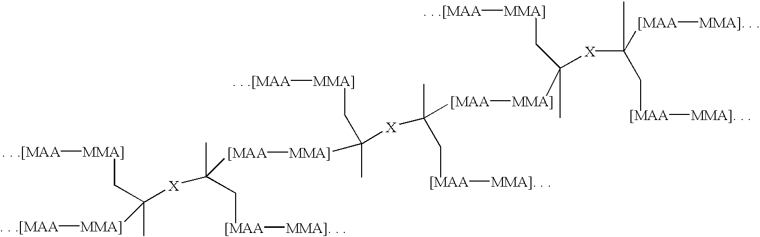
Branched Binder 1: A monomer mixture of 25% methacrylic acid, 71.5% methyl methacrylate, 3.5% of a moiety containing base cleavable functionalities having the formula pdmbi-pcp0200-pdmbi, where the “dashes” represent urethane linkages was diluted to 36% by weight with methyl ethyl ketone and then brought to reflux. An initiator was added to initiate the polymerization reaction. Periodic additions of initiator were added thereafter until the monomers were polymerized. The resulting branched binder had the generalized structure:

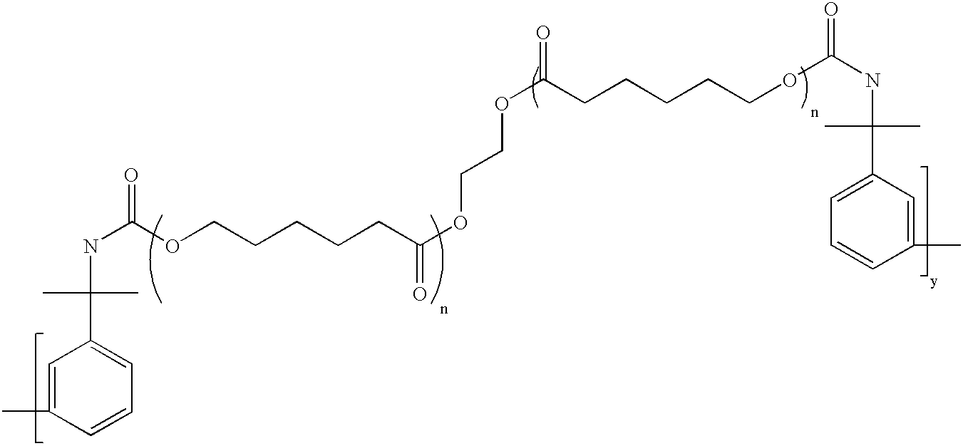
wherein X has the generalized structure:

and wherein y=1 and n=2. In the above structure, MMA...

example 2

Photoresist compositions were prepared by combining the polymer binders from Example 1 (53 wt %) with bisphenol A 10 ethoxy dimethacrylate monomer (43 wt %), commercially available initiator 1 (3.5 wt %), commercially available initiator 2 (0.05 wt %), green background dye (0.05 wt %), antioxidant (0.2 wt %) and flow additive (0.2 wt %). The above ingredients were mixed to a 50% solids mixture in a 4:1 mixture of methyl ethyl ketone and iso-propanol. After mixing for 2 to 4 hours using a lab mixer, the 50% solids mixture was dried on 0.8 mil thick polyester at approximately 80° C. for 3 to 9 minutes. The 50 micron thick, dried photoresist (less than 1.0% residual solvents) was then covered with 1.0 mil thick polyethylene forming a package of polyester / resist / polyethylene (finished “dry film”).

example 3

The negative working, photoresist composition from Example 2 was hot roll laminated to a cleaned, copper clad panel. The laminated panel were then covered with an artwork (phototool) and imaged with UV radiation using an Optibeam 7100 with enough energy to achieve a copper step 9 using a Stouffer 21 Step Wedge. After exposure, the polyester sheet was removed and the resist was then developing in 1% sodium carbonate monohydrate at 30° C. In the development process, the unexposed resist was removed. After development, the remaining (exposed) lines were examined for defects. The smallest lines with no defects and with 400 microns spaces were recorded as the fine line adhesion. Smaller lines are more easily attacked in the developing solution and by the conveyor equipment, thus a lower number indicates better adhesion. After examining the developed lines, the panels were then plated in a copper sulfate electrolytic plating bath until the resist height (50 microns) was exceeded by 20% (6...


PUM

PropertyMeasurementUnit
molecular weightaaaaaaaaaa
compositionaaaaaaaaaa
acid numberaaaaaaaaaa

Abstract

Disclosed are photoimageable compositions having improved stripping properties as well as methods for manufacturing printed wiring boards using such photoimageable compositions.

Description

BACKGROUND OF THE INVENTIONThis invention relates generally to the field of photoresists. In particular, this invention relates to the field of photoresists having improved stripping properties, especially suitable for use in printed wiring board manufacture.Photoresists are photosensitive films used for transfer of images to a substrate. A coating layer of a photoresist is formed on a substrate and the photoresist layer is then exposed through a photomask to a source of activating radiation. The photomask has areas that are opaque to activating radiation and other areas that are transparent to activating radiation. Exposure to activating radiation provides a photoinduced chemical transformation of the photoresist coating to thereby transfer the pattern of the photomask to the photoresist-coated substrate. Following exposure, the photoresist is developed to provide a relief image that permits selective processing of a substrate.A photoresist can be either positive-acting or negative...

Claims


Application Information

Patent Timeline
Patent Type & Authority Patents(United States)
IPC IPC(8): G03F7/30G03F7/20G03C1/73G03F7/028G03F7/032G03F7/004G03F7/027C08F220/14G03F7/029G03F7/031G03F7/033G03F7/035
CPCG03F7/033G03F7/035Y10S430/117Y10S430/107Y10S430/108Y10S430/111Y10S430/106G03F7/032
Inventor WHEELER, STEPHEN H.KAUTZ, RANDALL W.BARR, ROBERT K.
Owner SHIPLEY CO LLC
Why Eureka
Try Eureka