
System for real time, non-invasive metrology of microfluidic chips

a microfluidic chip and metrology technology, applied in the field of real-time, non-invasive metrology of microfluidic chips, can solve the problems of inability to achieve, and inability to achieve fluorescence-based imaging in a plane. achieve the effect of high throughpu

Inactive Publication Date: 2005-03-15
RGT UNIV OF CALIFORNIA
View PDF3 Cites 23 Cited by
  • Summary
  • Abstract
  • Description
  • Claims
  • Application Information

AI Technical Summary

Benefits of technology

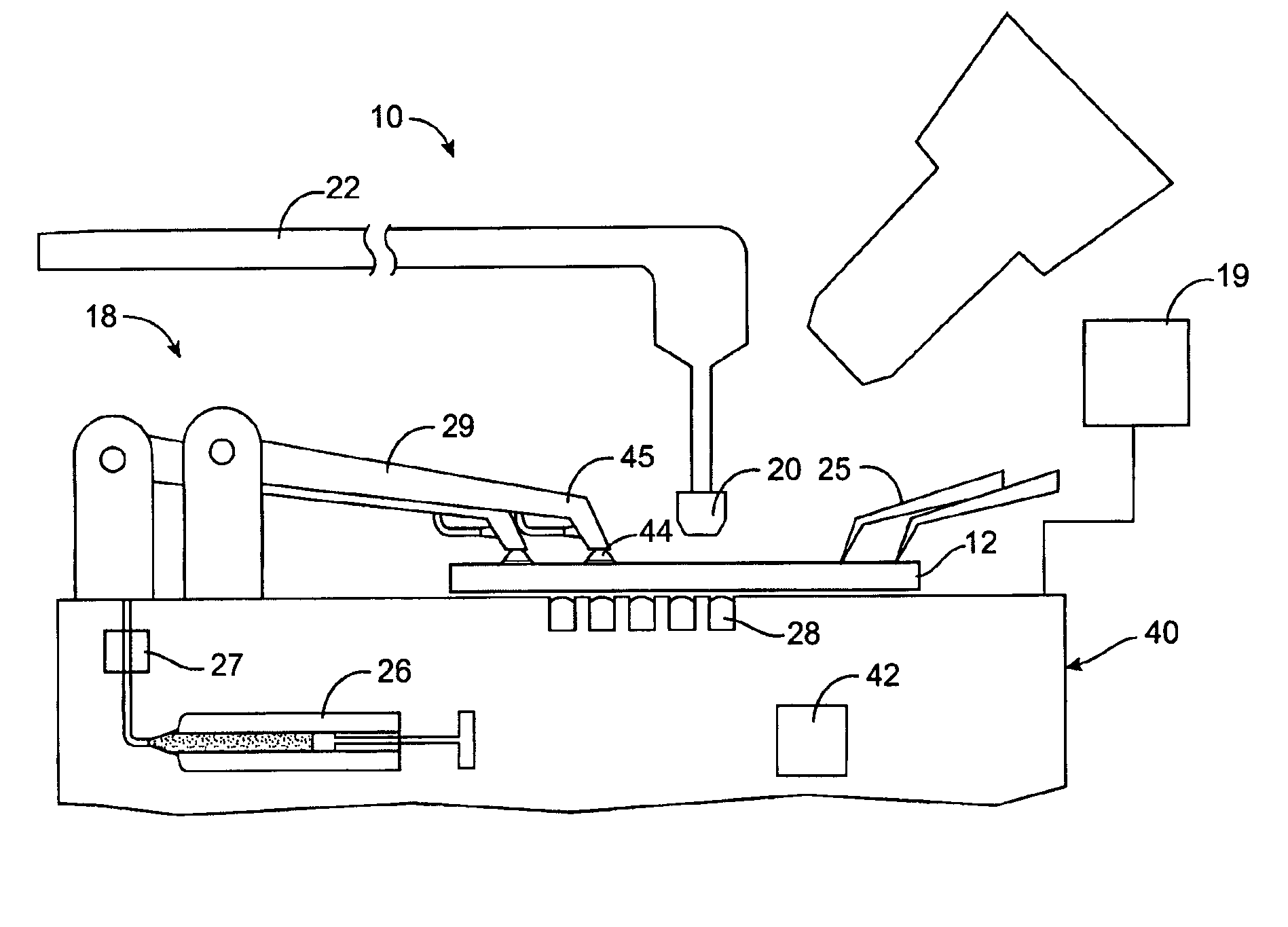
The invention is a system integration of multicomponent technologies in microfluidic systems. The invention includes the development of a sophisticated, automated microfluidic probe station and the subsequent use of that tool for the systematic study of nonideal, nonhomogeneous biological fluids such as blood in microfluidic chips. The technology of probe station allows for automated, high throughput testing and evaluation of microfluidic chips during and after manufacturing. The in-depth fluidics study resulting from the use of probe station provides a better understanding of non-ideal, non-homogeneous fluid flow in common chip components by providing the experimental data needed for perfecting accurate modeling algorithms and providing databases needed for the “device libraries” of computer aided design software. This result would not be possible without the development of the automated microfluidic probe station. Thus, the smart probe station provides for real-time, non-invasive metrology of microfluidic chips.
Using an ODT-based probe station, test devices on microfluidic wafers can be monitored for better process control. During packaging, test fluids can be injected into the chip to ensure proper functioning. Since the probe head in the present invention is a light source, testing can also be performed under extreme conditions (e.g., temperature, pressure, corrosive environments) to ensure that parts meet desired specifications. Furthermore, ODT can probe at different depths, allowing components on all layers of a three dimensional chip to be tested and characterized.
An object of the present invention is to provide a systematic study of non-ideal, non-homogeneous fluid flow in microfluidic chip components. Specifically, the nature of blood flow in microfluidic channels, valves, pumps, mixing chambers, and separation channels is revealed. In an illustrated embodiment polymer-based systems were laminated together to form complex integrated chips. The study is based on our ability to quickly, non-invasively characterize the fluid flow within microchannels using Optical Doppler Tomography (ODT), and our ability to rapidly manufacture many polymer microfluidic chips from a variety of different designs. Accordingly, it is yet another object of the present invention to be able to simulate different bio-microfluidic, non-ideal systems of interest.
The present invention is not soley directed to novel component technologies or microfluidic inventions, but includes all existing designs. Nor is there any requirement to optimize any specific component design. Instead, what is provided is some solid engineering groundwork to enable new inventions and designs to be developed for biological fluid systems. The system of the invention allows for the ability to develop engineering practices, standards and “rules of thumb” for phenomena relating to microfluidic design.

Problems solved by technology

This result would not be possible without the development of the automated microfluidic probe station.
Other techniques such as a fluorescence-based imaging are not likely to be as successful as ODT for this application, although in some applications it may be employed as an equivalent substitute for ODT.
Such fluorescence-based techniques are only good for imaging the flow in a plane and not specific for biological fluids such as blood.
Furthermore, these techniques are limited by a lack of depth resolution for imaging the flow and the requirement that the chip material be transparent.

Method used


Image

  • System for real time, non-invasive metrology of microfluidic chips
  • System for real time, non-invasive metrology of microfluidic chips
  • System for real time, non-invasive metrology of microfluidic chips

Examples


Embodiment Construction

1. The System

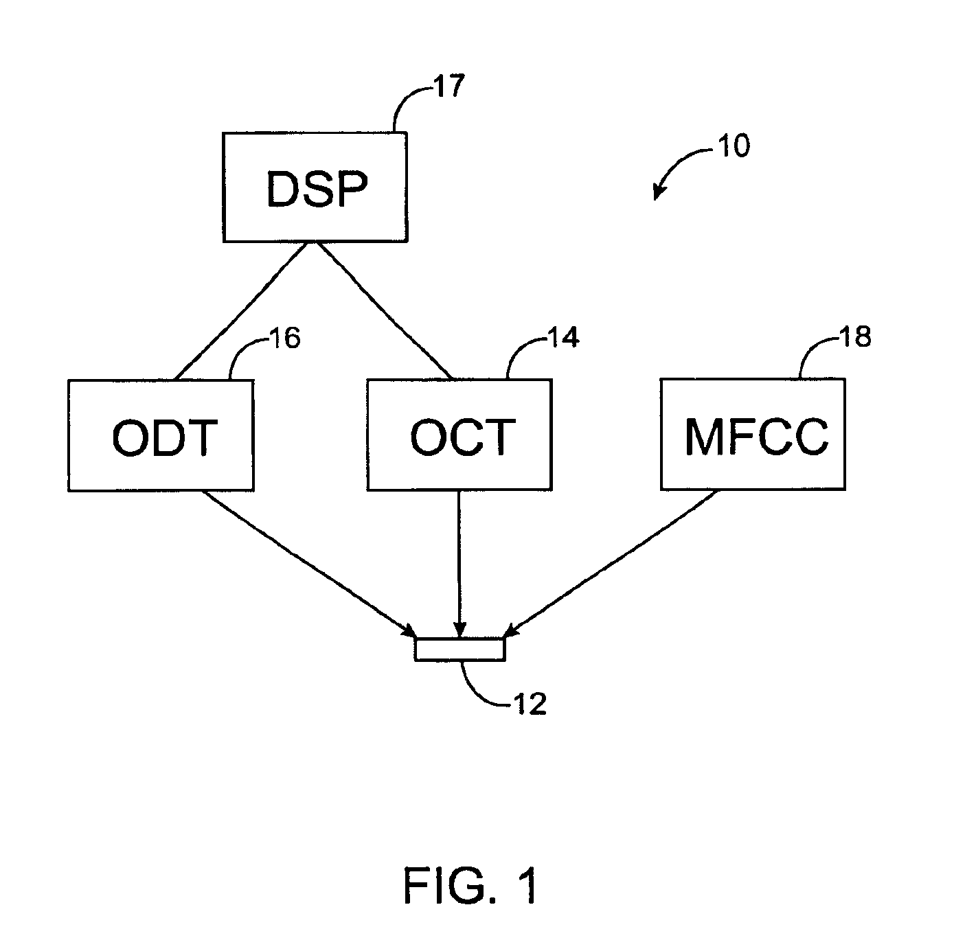
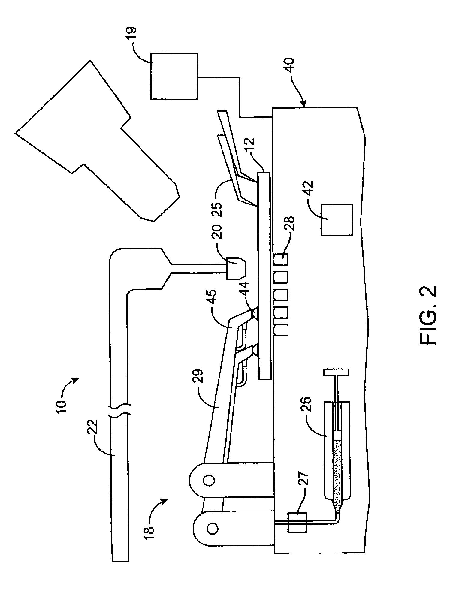
As shown in FIG. 1 smart microfluidic probe station 10 comprises an Optical Coherence Tomography (OCT) subsystem 14, Optical Doppler Tomography (ODT) subsystem 16, and a microfluidic chip controller (MFCC) 18. MFCC 18 allows fluids to be loaded into the BioFlips 12 at preprogrammed pressures, and provides actuation for certain on-chip components such as valves and pumps. The OCT / ODT subsystems 14, 16 are capable of providing simultaneous multiple point measurements of flow of various fluids in multiple layers of a three-dimensional biological microfluidic chip 12, including biological fluids such as blood, serum, interstitial fluids or saliva.

ODT / OCT based probe station 10 is suitable for microfluidic biochip manufacturing and testing purposes and will enable the development of practical manufacturing technology for biochips 12. Probe station 10 will not only identify design flaws of Bio-Flips 12 in the development phase, but also critically evaluate the manufacturabili...


PUM

PropertyMeasurementUnit
diameteraaaaaaaaaa
pixel sizeaaaaaaaaaa
acoustic wavelengthsaaaaaaaaaa

Abstract

A system integration of multicomponent technologies includes an automated microfluidic probe station and the use of that station for the systematic study of nonideal, nonhomogeneous biological fluids such as blood in microfluidic chips. The probe station provides for real-time, non-invasive metrology of microfluidic chips employing optical coherence tomography and optical Doppler tomography to allow for collection of flow data at any location or depth within a microfluidics chip. Also included is a programmable fluidic loader and actuator platform as part of the probe station, and a semi-automated rapid prototyping tool used to fabricate the microfluidic chips measured on the probe station. The resulting data library produced by measurements on the probe station contains all the necessary information needed to develop mature, accurate microfluidic modeling and simulation CAD tools.

Description

BACKGROUND OF THE INVENTION1. Field of the InventionThe invention is directed to the field of rapid prototyping, testing, characterizing and archiving performance parameters of microbiochips using actual body fluids.2. Description of the Prior ArtIn all fields of engineering practice, designers rely on common tools to efficiently design and produce functional working pieces. These tools include standardized manufacturing techniques, fully developed design rules and principles, databases of material properties, and visualization tools. In the past 30 years, most of these tools have been integrated into one delivery system, namely the computer. Computer aided design, in the form of modeling and simulation, is the predominant mode for performing complex engineering design.Unfortunately for biofluidic technologies, these tools are in their infancy. Although the fundamental physics of small-scale fluidic flow is understood, the physical phenomena which occur due to surface effects, elect...

Claims


Application Information

Patent Timeline
Patent Type & Authority Patents(United States)
IPC IPC(8): G01B9/02G16Z99/00
CPCG01B9/0201G01B9/02045G01B9/02027G01B9/02072G01B9/02091G01B2290/70G01B2290/45G01B2290/35G16Z99/00
Inventor LI, GUANN-PYNGBACHMAN, MARKCHEN, ZHONGPING
Owner RGT UNIV OF CALIFORNIA
Learn More