
Rolling device

a technology of rolling device and guide rail, which is applied in the direction of bearings, shafts and bearings, bearings, etc., can solve the problems of guide rail fracture, difficulty in application and inapplicability to the electronic part mounting apparatus or the wire bonding apparatus described above. , to achieve the effect of increasing the cos

Inactive Publication Date: 2005-04-05
NSK LTD
View PDF22 Cites 13 Cited by
  • Summary
  • Abstract
  • Description
  • Claims
  • Application Information

AI Technical Summary

Benefits of technology

The solution provides a rolling device with improved durability and long-term stability under high-speed and corrosive conditions, reducing wear and thermal-induced errors, while maintaining high positioning accuracy and resistance to radial loads.

Problems solved by technology

However, in the linear motion guiding device disclosed in Japanese Published Unexamined Patent Application No. 175691 / 1987, the guide rail is formed of a ceramic material having a specific rigidity of 0.8×108 mm or more and its application to the electronic part mounting apparatus or the wire bonding apparatus has been difficult by the following reasons.
On the contrary, since the linear motion guiding device disclosed in the publication above has a constitution of fixing both ends of the guide rail on the supporting bed or the like and moving the slider in use, it is not suitable to the application to the electronic part mounting apparatus or wire bonding apparatus described above.
Further, when a large bending moment is loaded on the guide rail, the guide rail is fractured in a case where the bending strength is insufficient even if the constituent material therefor is alumina ceramics, silicon carbide ceramics or silicon nitride.
Accordingly, it is difficult to increase the speed of the apparatus by merely forming the guide rail of ceramics regarding the reliability in view of the strength(particularly, reliability to bending strength).
Accordingly, it is difficult to increase the speed of the apparatus by merely constituting the guide rails with ceramics in view of the reliability for the strength (particularly, bending strength).
Further, while the rigidity of the rail per se is increased by forming the rail material of ceramic material, surface contact pressure with a rolling member incorporated in a slider increases, which increases the load on the rolling member compared with a case of using a rail formed of steels.
For example, when silicon nitride is used as the rail material and the rolling element is constituted with martensitic stainless steel, a difference of twice or more is caused for the hardness between them and wear of the rolling element is sometimes accelerated compared with a case of using a rail formed of steels.
However, when the guide rail rotates while moving vertically at a high speed as in the electronic part mounting apparatus or wire bonding apparatus, large inertia force is generated by acceleration or own weight of the rail and the head weight, and the driving performance(cycle speed, response performance) is deteriorated by the inertia force.
Further, since the inertia force is also increased when the density(mass) of the guide rail is large in this case, the bending strength of the guide rail is insufficient to sometimes result in fracture even in a case of using the cermet or cemented carbide as the rail material.
Further, when the ceramic material(particularly, usual silicon nitride) is used as the rail material, the heat conductivity is low and heat tends to be accumulated in the inside of the apparatus.
That is, when the guide rail is formed of a ceramic material of poor heat conductivity such as silicon nitride, since the temperature on the sliding surface of the guide rail becomes higher during operation and the grease viscosity lowers due to the temperature elevation on the rail sliding surface compared with a case of using iron and steel material such as bearing steels as the rail material, formation of oil membranes between the rolling element and the surface of the rail groove is inhibited to cause wear or minute seizure of the rolling element.
They cause generation of vibrations during operation of the linear motion guiding device, giving undesired effects on the accuracy in the repetitive positioning.
Further, temperature elevation of the rail material accelerates thermal expansion of the guide rail, which also gives undesired effects on the accuracy in the repetitive positioning.
Further, in view of increase in the diameter of wafers or liquid crystal panels, it results in the requirement for the rolling device to support larger load.
However, in the rolling bearing described in Japanese Published Unexamined Patent Application No. 121488 / 1996, since the outer ring is manufactured by an atmospheric pressure sintering process, it involves the following problems.
That is, a member manufactured by the atmospheric pressure sintering process has low strength and fracture toughness in which micro-cracks tend to develop starting from the surface or internal.
Accordingly, a great amount of abrasion powder is formed or cracks are resulted to sometimes shorten the life of the rolling bearing.
Particularly, when the rolling bearing supports a radial load, since the load is concentrated to a load region of the outer ring, cracks propagate easily in the load region of the outer ring manufactured by the atmospheric pressure sintering process even under a slight load to sometimes shorten the life extremely.
Further, in a case where the inner ring, the outer ring and the rolling elements are constituted with silicon carbide as in the rolling bearing described in Japanese Published Unexamined Patent Application No. 82426 / 1998, although the corrosion resistance is excellent, it involves a problem that the strength and the fracture toughness are low.
When a load exerts to some extent on the rolling bearing, cracks propagate on the surface or through the entire portion to sometimes cause flaking or cracking.
Particularly, when the rolling bearing supports a radial load, since the load is concentrated in the load region of the outer ring, flaking and cracking occur to sometimes shorten the life extremely even under a slight load.
Accordingly, under severe working conditions at high speed rotation, particularly, the radial gap of the bearing is excessively small or a preload becomes excessive by the change of the gap to sometimes bring about seizure or shorten the working life extremely.
However, in a case where rotational conditions changes variously, and heat generation is large in the inside of the bearing or external heat is conducted to cause a temperature difference in the inside of the bearing, the gap in the inside of the bearing or the preload caused by the change of the gap may be adjusted by an external force(for example, by oil pressure mechanism) by detecting the temperature of the bearing assembled into the rotational device, but this involves a drawback that the device is complicated and becomes expensive.
However, as the rotational speed increases and the heat generation increases to increase the temperature gradient in the rolling device, since the rolling element is formed of a bearing steel of the same material as that for the outer ring and the amount of thermal expansion is large, even if the amount of thermal expansion of the inner ring is less than the amount of the thermal expansion of the outer ring, the gap becomes insufficient to cause seizure or to sometimes shorten the life excessively.
Further, while Japanese Published Unexamined Patent Application No. 205276 / 2000 discloses a rolling bearing in which the heat conductivity of the ceramic material constituting the outer ring is made larger than the heat conductivity of the ceramic material constituting the inner ring and the rolling element, the rolling bearing described in this publication involves the following problems.
That is, since some of the ceramic materials are insufficient in the thermal impact resistance or bending strength, when they are used in a high temperature atmosphere or high temperature / corrosive atmosphere, a temperature gradient is caused in the bearing and thermal stresses are generated by the temperature gradient.
Then, micro-cracks propagate on the surfaces of the outer ring or the inner ring to sometimes form a great amount of abrasion powder, or cracks penetrate the member to cause breakage to shorten the working life of the rolling bearing.
Even when the rolling bearing is constituted with Si3N4, SiC, Al2O3 or sialon, when the thermal impact resistance value or bending strength is insufficient, micro-cracks propagates on the surface of the constituent members to cause a great amount of abrasion powder or cracks penetrate the constituent members to sometimes cause breakage.

Method used


Image

  • Rolling device
  • Rolling device
  • Rolling device

Examples


embodiment 1

[Embodiment 1]

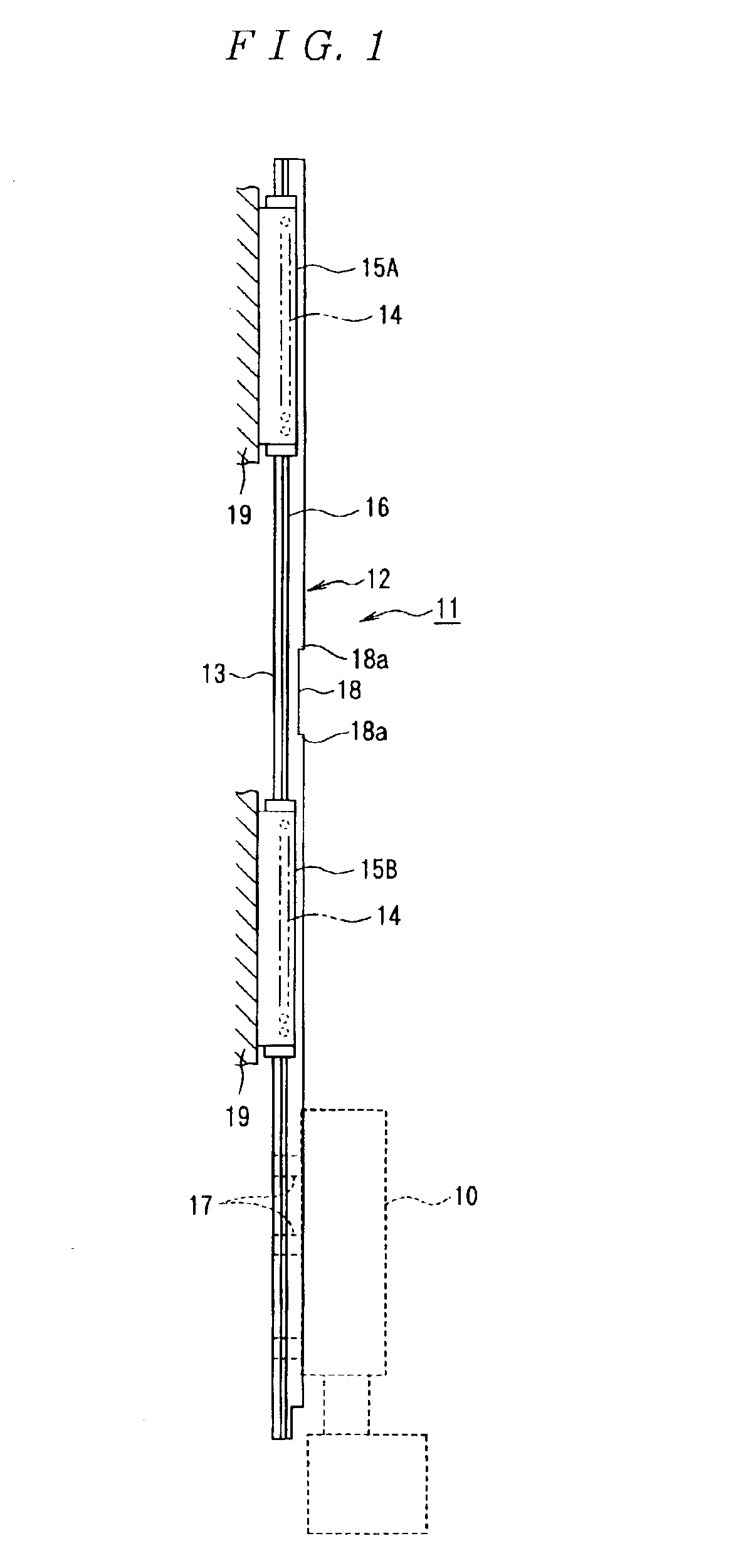
FIG. 1 is a view showing a linear motion guiding device as an embodiment of a rolling device according to this invention. In the drawing, reference numeral 10 denotes an electronic part suction head, and 11 denotes a head lifting mechanism for vertically reciprocating the electronic part suction head 10, in which the head lifting mechanism 11 comprises a driving device (not illustrated) and a plurality of linear motion guiding devices 12 disposed at the periphery of the driving device.

The linear motion guiding device 12 comprises a guide rail 13 as a support or a movable member, spherical rolling elements 14 and sliders 15A and 15B as a movable member or a support, and rolling grooves 16 of rolling element are formed on both lateral sides of the guide rail 13 along the longitudinal direction of the guide rail 13. The rolling groove 16 of rolling element is used for guiding the spherical rolling elements 14 in the longitudinal direction of the guide rail 13 and has a su...

embodiment 2

[Embodiment 2]

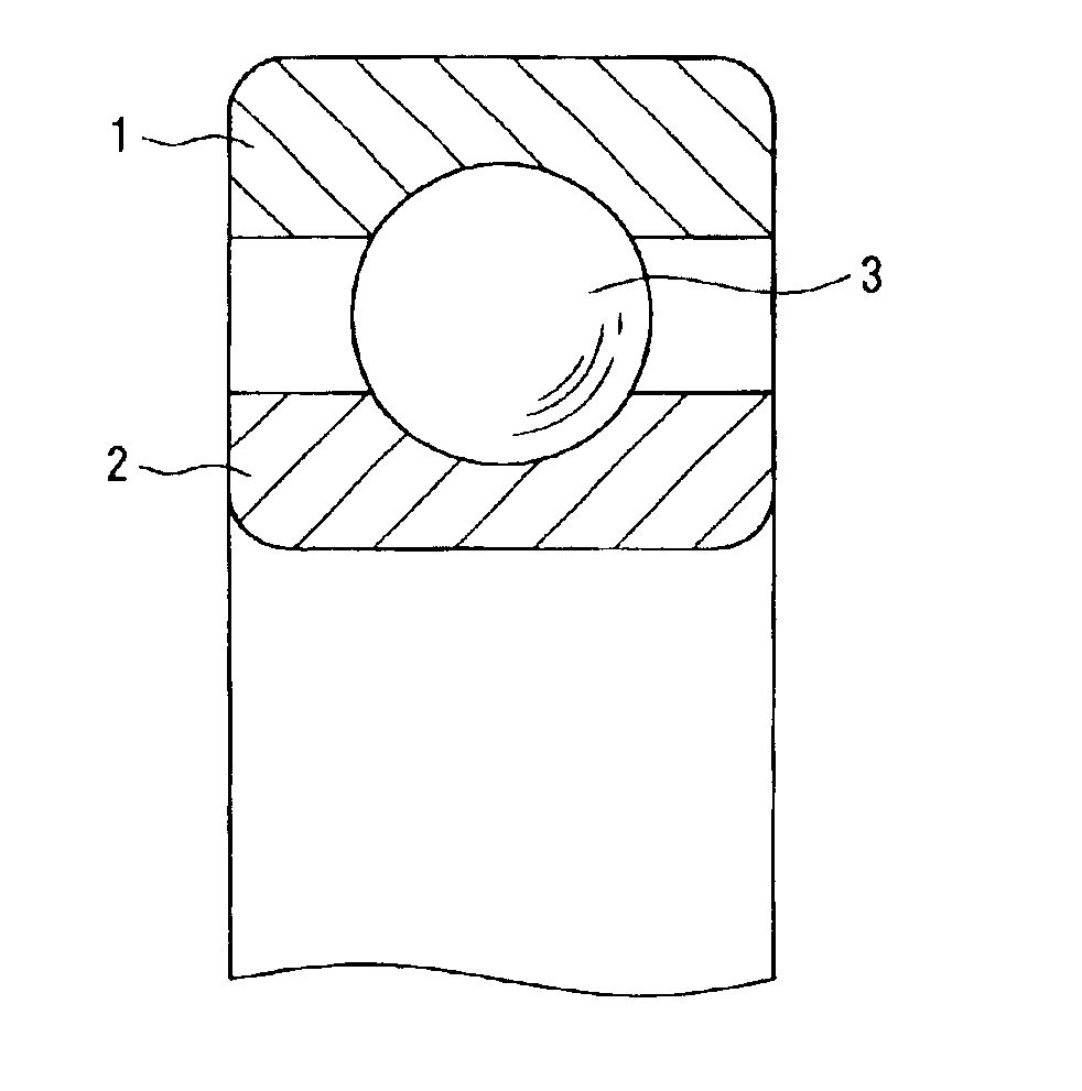
FIG. 21 is a fragmentary vertical cross sectional view showing the structure of a deep groove ball bearing as an embodiment of a rolling device according to this invention.

The ball bearing comprises an outer ring 1, an inner ring 2, a plurality of balls 3 disposed rotationally between the outer ring 1 and the inner ring 2, and a snap cage formed of resin (not illustrated) for holding a plurality of balls. In this case, the outer ring 1 corresponds to the support as a constituent factor of the invention and the inner ring 2 corresponds to the movable member as a constituent factor of the invention.

All of the outer ring 1, the inner ring 2 and the ball 3 are constituted with ceramic material, cermet or cemented carbide. The specific strength of the ceramic material, the cermets and the cemented carbide is 1.2×107 mm or more. Further, the thermal impact resistance value of the ceramic material, the cermet and the cemented carbide is 1.5 times or more of the working circum...

embodiment 3

[Embodiment 3]

FIG. 26 shows a rolling bearing as a rolling device according to this embodiment in which rolling elements 3 are interposed between a raceway surface 1a of an inner ring 1 (guiding surface) and a raceway surface 2a (guiding surface) of an outer ring 2.

The outer ring 2 is attached to a housing 4 to constitute a support and the inner ring 1 is secured to the shaft 5 to constitute a movable member.

The inner ring 1 and the outer ring 2 are formed of bearing steels such as SUJ2 or SUS4040C.

Further, the rolling element 3 is formed of a ceramic material or a cemented carbide, and each of the ratio of the linear expansion coefficient of the rolling element 3 to the inner ring 1 and the ratio of the linear expansion coefficient of the rolling element 3 to the outer ring 2 is set to 0.45 or less by selecting the ceramic material or the cemented carbide.

In the rolling bearing having the constituent described above, the thermal expansion amount of the rolling element 3 is outstand...


PUM

PropertyMeasurementUnit
fracture toughnessaaaaaaaaaa
particle sizeaaaaaaaaaa
fracture toughnessaaaaaaaaaa

Abstract

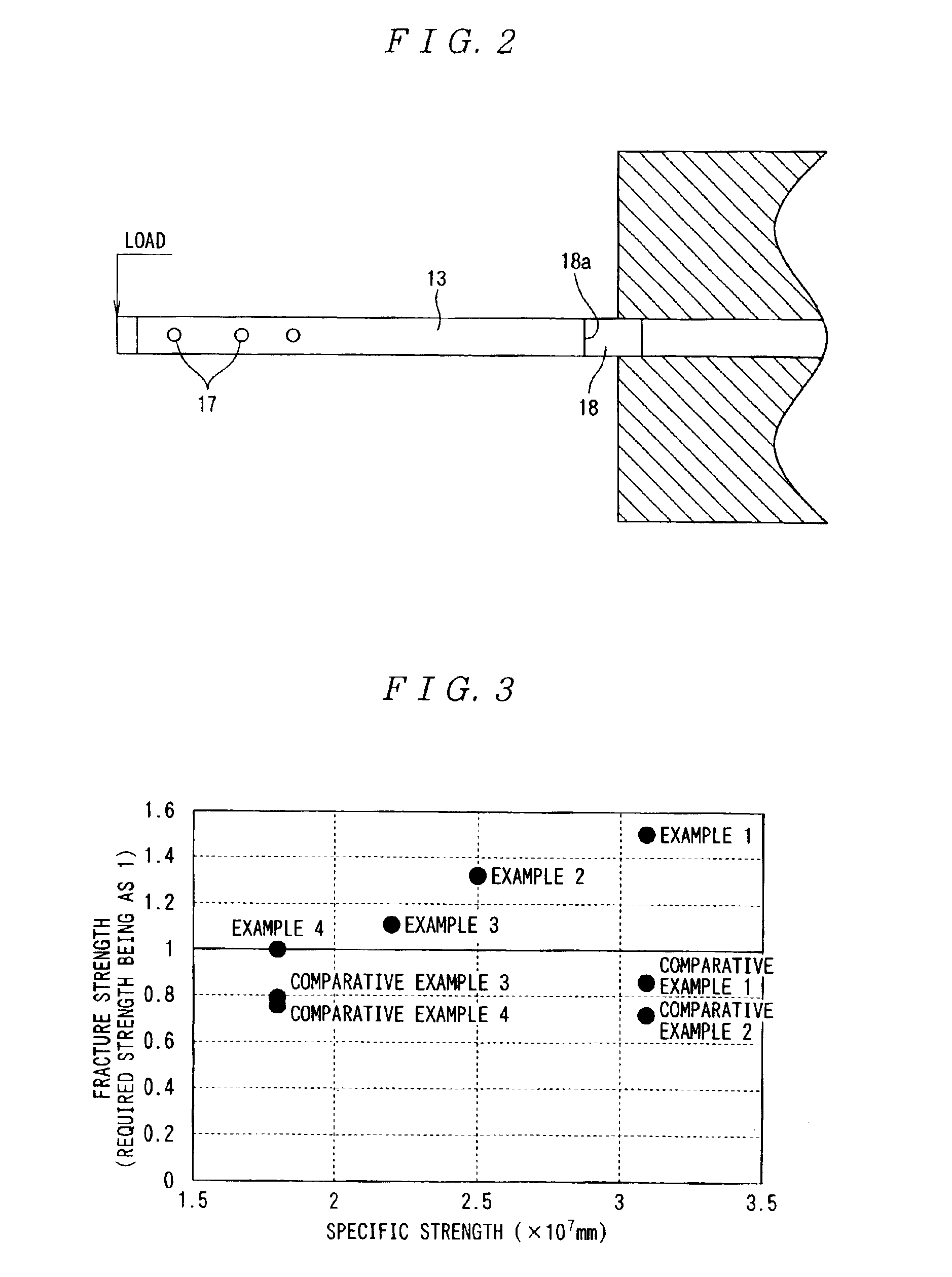
A guide rail 13 is formed of a ceramic material having a specific strength of 2×107 mm or more and has a planar part with a surface roughness of 0.5 μmRa or less. Further, the guide rail 13 has a recess 18 for avoiding interference with a part to be attached in which the corner 18a of the recess 18 is formed with a radius of curvature of 0.1 mm or more.

Description

TECHNICAL FIELDSThis invention relates to a rolling device such as a rolling bearing, a linear motion guiding device or a ball screw and, more in particular, it relates to a rolling device that can be used under high load at high speed, in a corrosive circumstance, high temperature circumstance or in a circumstance supporting a radial load, such as in various kinds of spindles, various kinds of pumps, semiconductor production apparatus (transportation apparatus and the like), machine tools and turbines.BACKGROUND ARTElectronic part mounting apparatus used, for example, in the process of producing electronic equipments such as computers or mobile telephones are adapted, for example, such that an electronic part suction head is disposed vertically movably above an X-Y table on which a substrate is placed and electronic parts are mounted at predetermined positions on the substrate by sucking electronic parts such as semiconductor devices by the head. Accordingly, for mounting electroni...

Claims


Application Information

Patent Timeline
Patent Type & Authority Patents(United States)
IPC IPC(8): F16C33/32F16C33/30F16C33/62F16C33/34F16C29/00
CPCF16C29/005F16C33/32F16C33/34F16C33/62F16C2206/82F16C2206/00F16C2206/60F16C2206/80F16C2240/48F16C2220/20F16C2240/54
Inventor YAMAMOTO, TOYOHISAIKEDA, NORIFUMIYAMAMOTO, KOUICHI
Owner NSK LTD
Learn More