Optical element

a technology of optical elements and synthetic resins, applied in the field of optical elements, can solve the problems of difficult aspheric configuration, and limited use of synthetic resins in optical designs

Inactive Publication Date: 2005-07-12
OLYMPUS CORP
View PDF8 Cites 3 Cited by
  • Summary
  • Abstract
  • Description
  • Claims
  • Application Information

AI Technical Summary

Problems solved by technology

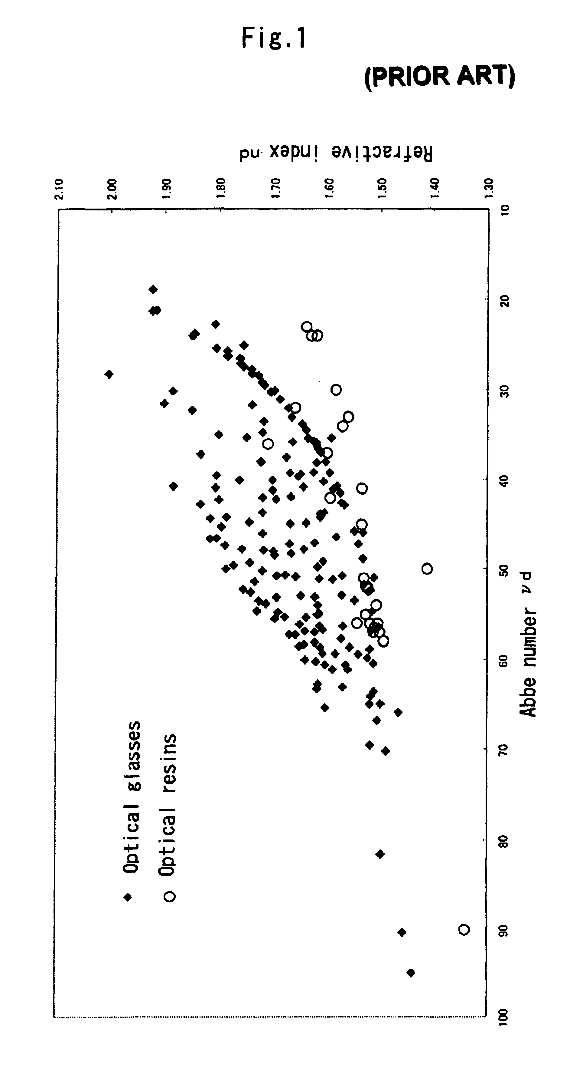
On the other hand, synthetic resins that may be used as optical materials are limited in terms of type and narrower than optical glasses in terms of the range of the optical properties to be selected, as shown in FIG. 1, and so optical designs using synthetic resins have many restrictions.
With cutting and polishing that is a typical method for processing conventional optical elements such as glass lenses, however, it is very difficult to configure aspheric forms, and so this method does not lend itself to mass production.
However, current commercial optical glasses having low refracting-index chromatic dispersions, because of being based on fluorophosphates, cause damage to the precisely processed molding surface of a mold under the influences of glass components when they are subjected to precise press molding at a high temperature at which they soften, making it difficult to maintain the surface precision of the molding surface of the mold.
Thus, mass-production of high-quality optical glasses is still difficult.
This causes the thickness deviation to become considerably large, resulting in an increase in the level of difficulty in molding processes.
For instance, precise press molding for glasses has a possibility of glass cracking upon drastic deformation given to the softening glass via the molding surface of the mold, and so renders it very difficult to mold and process lenses having too large a thickness deviation.
As shown in FIG. 1, however, the synthetic resins are not only narrow in the range of optical properties but also provide an optical element that is poor in environmental stability due to a high rate of thermal expansion and hygroscopic deformation depending on composition.
Thus, the synthetic resins have a problem in that they are unsuitable for mass production.

Method used


Image

  • Optical element
  • Optical element
  • Optical element

Examples


example 1

[0046]A fluororesin (TVH220 made by Dainion Co., Ltd. with a melting point of 110 to 130° C.) obtained by copolymerization of tetrafluoroethylene-hexafluoropropane-vinylidene fluoride soluble in solvents based on lower ketones or esters was dissolved as the organic component in methyl ethyl ketone to prepare a solution having a 10% by mass concentration.

[0047]A solution (55.8 parts by weight) wherein methyltrimethoxysilane and methacryloyloxypropyltrimethoxysilane were mixed together with at a molar ratio of 8:2 was dissolved in 30 parts by weight of acetone, and the solution was stirred at room temperature for 24 hours with the addition of water in an amount of 18.9 parts equivalent to the methoxy group, thereby obtaining an inorganic polymer component solution. This solution was well mixed and stirred with a solution of fluororesin in methyl ethyl ketone while the ratio of the fluororesin to the mass of the nonvolatile matter in the aforesaid solution was 1:9 (by mass), thereby pr...

example 2

[0057]Transparent sheets of 4 mm in thickness were obtained as in Example 1 with the exception that calcium fluoride fine particles having an average particle diameter of 70 nm were used in place of the magnesium fluoride fine particles. The results obtained at varying calcium fluoride contents are tabulated below.

[0058]

TABLE 2Organic / inorganic hybridRefractiveAbbematerial vs. calcium fluorideindexnumber(ratio by mass)(nd)(vd)70:301.3778380:201.3708190:101.36079

[0059]In this case, too, low refractive-index chromatic dispersion characteristics were obtained. As in Example 1, the transparent sheet of 4 mm in thickness was compression molded at 230° C. while it was placed in a mold having a concave surface and a convex surface. As a result, a lens of the same concave meniscus shape could be molded into an optical element.

example 3

[0060]Methyltriethoxysilane and methacryloyloxypropyltrimethoxysilane were mixed together at a molar ratio of 8:2 to prepare a solution. Eighteen point nine (18.9) parts by weight equivalent to the alkoxy groups were added to 55.8 parts by weight of that solution, and the solution was stirred at room temperature for 20 hours for poly-condensation of the alkoxy groups. Then, 5.7 parts by weight of hydroxyethyl methacrylate were added and the solution was charged in an evaporator where volatile matter was removed at 40 to 50° C., thereby preparing an inorganic component solution. Then, a photopolymerization initiator Irgacure 149 was added to a methyl methacrylate monomer at 0.5:100 (by mass) to prepare a solution. This solution was mixed with the same weight of the inorganic component solution to obtain an organic / inorganic hybrid material solution.

[0061]Fifty (50) parts by weight of this solution were mixed with 50 parts by weight of magnesium fluoride fine particles having an avera...


PUM

PropertyMeasurementUnit
sizeaaaaaaaaaa
Abbe numberaaaaaaaaaa

Abstract

The invention provides an optical element that has a low refractive-index chromatic dispersion, a high degree of freedom in molding or forming as is the case with synthetic resins, and moldability or formability that lends itself to mass production. The optical element is obtained by molding or otherwise forming a composition containing a first material that is a fine particle having an Abbe number vd of 80 or greater indicative of a chromatic dispersion in a visible range and having a size of less than 400 nm, and a second material that is an organic / inorganic hybrid material comprising an organic polymer material having a carbon-carbon bond in a main chain and an inorganic component.

Description

BACKGROUND OF THE INVENTION[0001]The present invention relates generally to an optical element obtained by configuring a material having satisfactory optical properties represented by refractive-index chromatic dispersion characteristics by molding or forming means into a given shape, for instance, lenses, prisms, filters, refracting optical elements and diffracting optical elements.[0002]So far, chromatic aberrations of dioptric systems have been corrected by combinations of optical materials having varying refractive-index dispersion characteristics. By making a selection from many optical materials having varying refractive indices and varying refractive-index chromatic dispersion characteristics for optical designs, the degree of freedom in the optical designs is so enhanced that chromatic aberration-free, high-precision optical systems can easily be designed.[0003]For such optical materials, there have been developed a variety of optical glasses having varying refractive indice...

Claims


Application Information

Patent Timeline
Patent Type & Authority Patents(United States)
IPC IPC(8): C08K3/00C08K3/16G02B1/04C08L27/12C08L83/04G02B1/00
CPCC08K3/16G02B1/04
Inventor SHIGA, NAOHITOOBI, KUNIHISAGOTO, ATSUSHITAKEYAMA, TETSUHIDESHIRAI, MICHIO
Owner OLYMPUS CORP
Why Eureka
Try Eureka