Zero-mode clad waveguides for performing spectroscopy with confined effective observation volumes

a technology of effective observation volume and zero-mode metal clad waveguide, which is applied in the direction of fluorescence/phosphorescence, material analysis through optical means, instruments, etc., can solve the problems of low efficiency of near-field fiber collection and very inefficient prior art, and achieve accurate metered sample quantity, facilitate the use of single chip, and facilitate the effect of small quantity

Inactive Publication Date: 2005-07-12
CORNELL RES FOUNDATION INC
View PDF7 Cites 756 Cited by
  • Summary
  • Abstract
  • Description
  • Claims
  • Application Information

AI Technical Summary

Benefits of technology

[0009]The apparatus of the present invention is used for analysis of an analyte. This includes a zero-mode waveguide having a cladding surrounding a core, where the cladding is configured to preclude propagation of electromagnetic energy of a frequency less than a cutoff frequency longitudinally through the core of the zero-mode waveguide. In addition, this apparatus has a source of electromagnetic radiation positioned relative to the zero-mode waveguide to direct electromagnetic radiation of a frequency less than the cutoff frequency into the core under conditions effective to permit analysis of an analyte in an effective observation volume which is more compact than if the analysis were carried out in the absence of the zero-mode waveguide.
[0010]In one embodiment of the present invention, the apparatus includes a superstructure contacted with the opaque film that serves to facilitate the use of a single chip with several different samples to be analyzed. In this embodiment, the zero-mode waveguides are positioned in an array such that several identical devices are spaced at equal intervals across the surface of the chip. The superstructure serves to isolate each device on the chip from all of the rest, allowing an individual device on a chip to be used with a particular sample without contaminating the rest of the devices on the chip.
[0011]In another embodiment of the present invention, a different superstructure is applied to a chip containing an array of zero-mode waveguide devices to facilitate the delivery of a small, accurately metered quantity of sample to each device on the chip. In this embodiment the superstructure contains microfluidic channels positioned to allow sample introduced at one or more input ports to be delivered to fluid cavities positioned over each of the zero-mode waveguide devices. The microfluidic portions of the superstructure can be use simply to convey and measure the sample, or more sophisiticated operations such as capillary electrophoresis can be performed on the sample before it reaches the zero-mode waveguide device for optical analysis.

Problems solved by technology

Only a very small percentage of light sent down the fiber makes it through the near-field aperture to the illumination region, making the prior art very inefficient.
Additionally, the spectroscopic signal from the analyte is best collected externally by an additional apparatus, such as a microscope objective, since the efficiency of collection by the near-field fiber is very low.

Method used


Image

  • Zero-mode clad waveguides for performing spectroscopy with confined effective observation volumes
  • Zero-mode clad waveguides for performing spectroscopy with confined effective observation volumes
  • Zero-mode clad waveguides for performing spectroscopy with confined effective observation volumes

Examples


example 1

Fabrication of Zero-Mode Waveguide Array

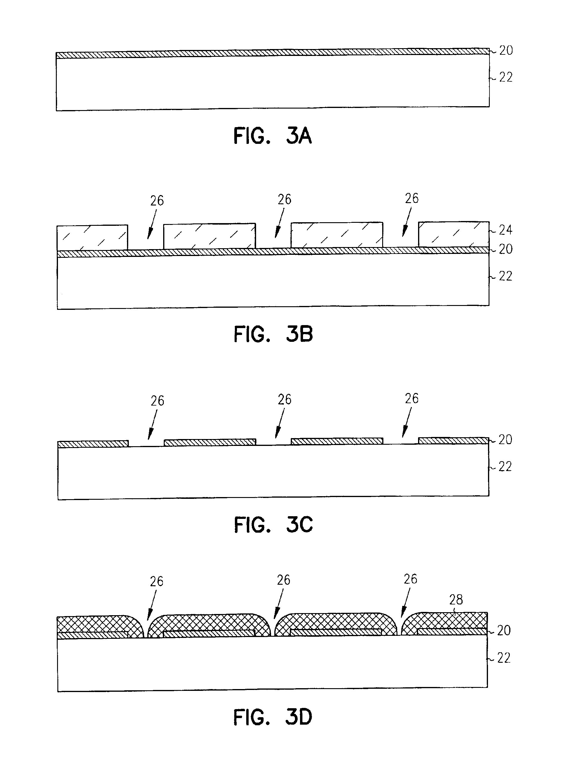
[0053]Arrays of zero-mode waveguides were manufactured as small holes in a 50 nm thick film of aluminum on a glass or fused silica coverslip. The steps for the fabrication of the devices are as follows. First, the cover glasses were cleaned with a solution of one part ammonium hydroxide, one part hydrogen peroxide, and six parts water at 70° C. The coverglasses were immersed in this solution for 10 minutes, and then rinsed in a overflowing bath of deionized water for 10 minutes. The samples were dried with compressed dry nitrogen and then subjected to oxygen plasma for 3 minutes. The cleaned cover glasses were then coated with 50 nm of aluminum by thermal evaporation. An electron beam lithography resist, ZEP-7000A, was spun onto the cover glasses for 60 seconds at 3000 RPM. Excess solvent was driven from the films by baking on a temperature-controlled hotplate for 30 minutes at 170° C. This process yields a film approximately 300 nm thick. The...

example 2

Intensity Evaluation with Zero-Mode Waveguide Array

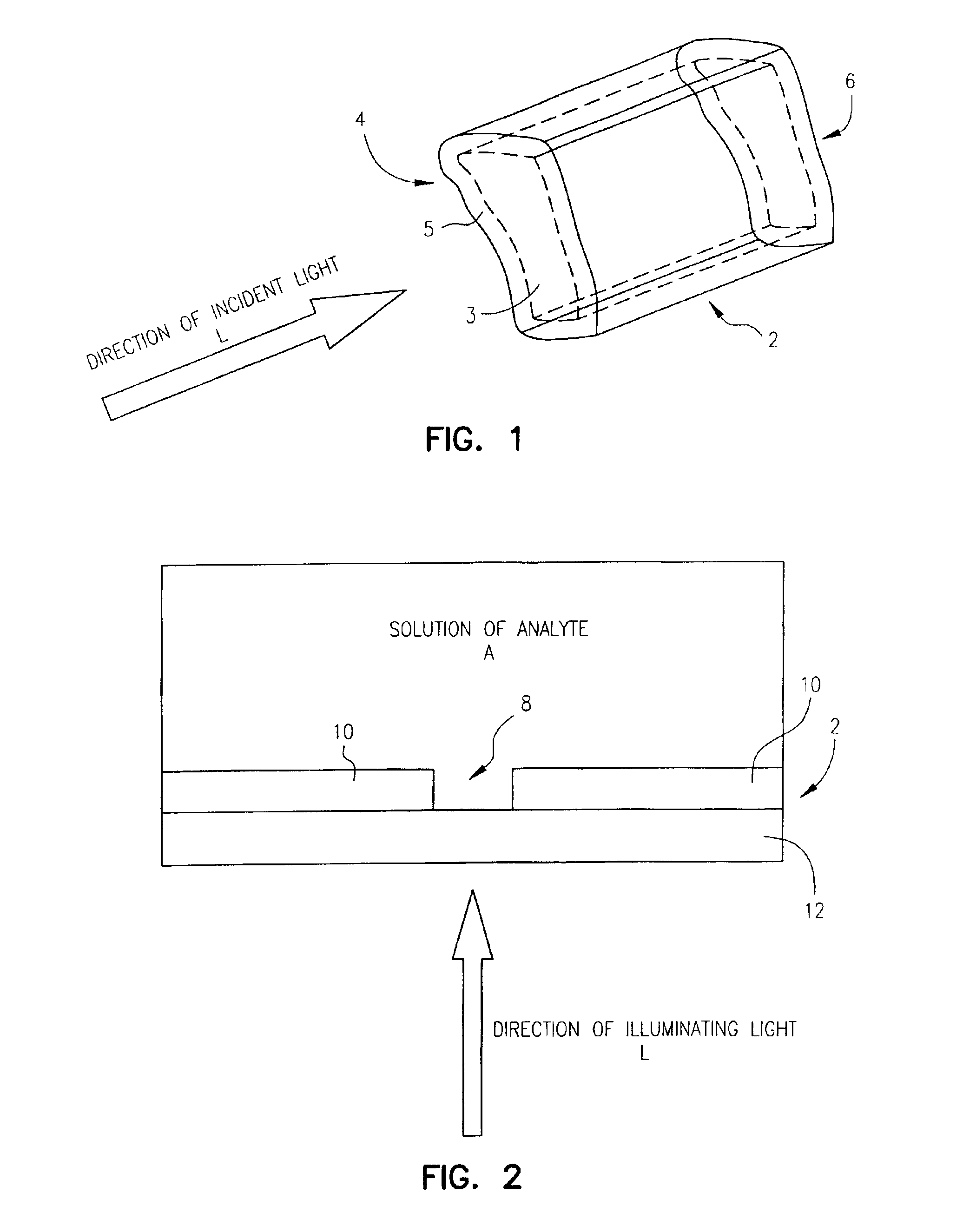
[0055]Simulations of the electric field inside zero-mode waveguides were performed using a commercial finite-element time-domain Maxwell's equation solver (EMFlex, from Weidlinger Associates, New York, N.Y.). Models were run for right, circular cylindrical waveguides of water in 50 nm thick aluminum films on a glass substrate (index of refraction 1.5). The entire region above the aluminum and inside the waveguides was assumed to be filled with water, and the illumination was, in all cases, normally incident circularly polarized plane waves of light at 6×10¹⁴ Hz (corresponding to a vacuum wavelength of 500 nm). The entire region of the model was 1 μm3, and the grid spacing inside and in the vicinity of the waveguides was 1 nm. Although actual experiments would in most cases use tightly focused light, rather than the plane waves modeled here, the dimensions of the waveguides modeled are small enough compared with the wavelength of lig...

example 3

Spectroscopy with Zero-Mode Waveguides

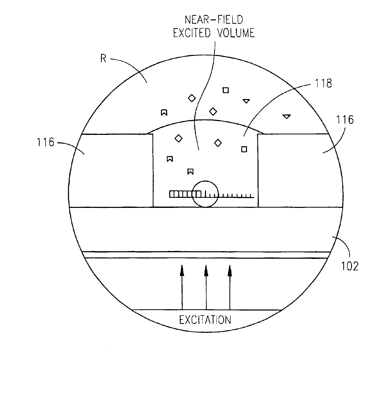
[0057]For fluorescence applications, one can define the size of effective observation volume, V, as V=∫S⁡(r)⁢ⅆ3⁢r⁢∫S⁡(r)⁢ⅆ3⁢r∫S2⁡(r)⁢ⅆ3⁢r

where S(r) is the observation efficiency at the point r, and for this system S(r)=12(r). FIG. 13 shows the effective volume of zero order waveguides in aluminum illuminated with 6×10¹⁴ Hz light as a function of waveguide diameter. Volumes are on the order of 50 zeptoliters (10−21 liters). This compares to 0.5 femtoliters (10−15) for a typical diffraction-limited focal volume.

[0058]The effectiveness of the waveguides in confining the volume of illumination was evaluated using fluorescence correlation spectroscopy (“FCS”). FCS involves illumination of a sample volume containing dye molecules in solution. The diffusion of molecules into and out of the effective observation volume leads to fluctuations in the number of observed molecules and hence to fluctuations in the fluorescence signal. These fluctuations occur...


PUM

PropertyMeasurementUnit
diameteraaaaaaaaaa
diametersaaaaaaaaaa
diameteraaaaaaaaaa

Abstract

The present invention is directed to a method and an apparatus for analysis of an analyte. The method involves providing a zero-mode waveguide which includes a cladding surrounding a core where the cladding is configured to preclude propagation of electromagnetic energy of a frequency less than a cutoff frequency longitudinally through the core of the zero-mode waveguide. The analyte is positioned in the core of the zero-mode waveguide and is then subjected, in the core of the zero-mode waveguide, to activating electromagnetic radiation of a frequency less than the cut-off frequency under conditions effective to permit analysis of the analyte in an effective observation volume which is more compact than if the analysis were carried out in the absence of the zero-mode waveguide.

Description

INCORPORARTION BY REFERENCE[0001]This application claims priority to U.S. Provisional Patent Application No. 60 / 325,280, filed Sep. 27, 2001, which is related to U.S. patent application Ser. No. 09 / 572,530, which are hereby incorporated by reference.[0002]This invention was made with funds provided by the U.S. Government under National Science Foundation Grant No. BIR8800278, and National Institutes of Health Grant No. P412RR04224-11, and Department of Energy Grant No. 066898-0003891. The U.S. Government may have certain rights in this invention.FIELD OF THE INVENTION[0003]The present invention is directed to zero-mode metal clad waveguides for performing spectroscopy with confined effective observation volumes.BACKGROUND OF THE INVENTION[0004]Observing and understanding the activity of a single molecule, such as an enzyme, is critical to understanding the dynamics of many important biochemical processes, such as catalysis, signal transduction, and gene regulation. Many biochemical ...

Claims


Application Information

Patent Timeline
Patent Type & Authority Patents(United States)
IPC IPC(8): G01N21/64G01N21/47G01N21/65G01N21/63G02B6/10G02B6/24G12B21/06G12B21/00G01Q60/18
CPCB82Y20/00B82Y35/00C12Q1/25G01N21/47G01N21/6408G01N21/6428G01N21/645G01N21/6452G01N21/65G01N33/54373G02B6/10G02B6/241G01Q60/22C12Q1/6825G01N2333/9015
Inventor LEVENE, MICHAEL J.KORLACH, JONASTURNER, STEPHEN W.CRAIGHEAD, HAROLD G.WEBB, WATT W.
Owner CORNELL RES FOUNDATION INC
Why Eureka
Try Eureka