
Carbon nano-particle and method of preparing the same and transparent conductive polymer composite containing the same

Active Publication Date: 2005-07-19
DONG WOON INT
View PDF16 Cites 50 Cited by
  • Summary
  • Abstract
  • Description
  • Claims
  • Application Information

AI Technical Summary

Benefits of technology

[0016]It is a second object of the present invention to provide a novel method for preparing the carbon nano-particle. So far, fullerenes, carbon nanotubes, etc. are conventionally prepared based on the vaporization / aggregation process of carbon atoms. However, in the method according to the present invention, the carbon nano-particle is prepared by a process step called as “Microemulsion polymerization” of polymer and a process step for carbonizing the resultant at a high temperature. The above method can be implemented at a low cost.
[0017]It is a third object of the present invention to provide a transparent and highly electric conductive polymer composite containing the carbon nano-particle. As described above, the carbon nano-particle according to the present invention has the high transparency even when it is added to a transparent polymer resin and also has the high electric conductivity.

Problems solved by technology

However, where carbon nanotubes are added to a transparent resin in order to prepare an optically-transparent, conductive film, a strong aggregate power is generated between carbon nanotubes during the coating process to black the film, so that the transparency of the resin is significantly decreased.
However, since the above method needs the use of a strong acid such as sulfuric acid, it makes the process difficult and also the composite containing such surface-treated carbon nanotubes has the transparency worse than Indium Tin Oxide (ITO).
Therefore, the so far known carbon nanotubes are not capable of effectively forming a transparent composite because of the limit of their size or the limit of methods of treating them.
Furthermore, since the so far developed methods include a step for evaporating carbon atoms, the carbon nanotubes prepared therefrom are relatively expensive; therefore, it is impossible to implement a mass production on the basis of these methods.

Method used


Image

  • Carbon nano-particle and method of preparing the same and transparent conductive polymer composite containing the same
  • Carbon nano-particle and method of preparing the same and transparent conductive polymer composite containing the same
  • Carbon nano-particle and method of preparing the same and transparent conductive polymer composite containing the same

Examples


example 1

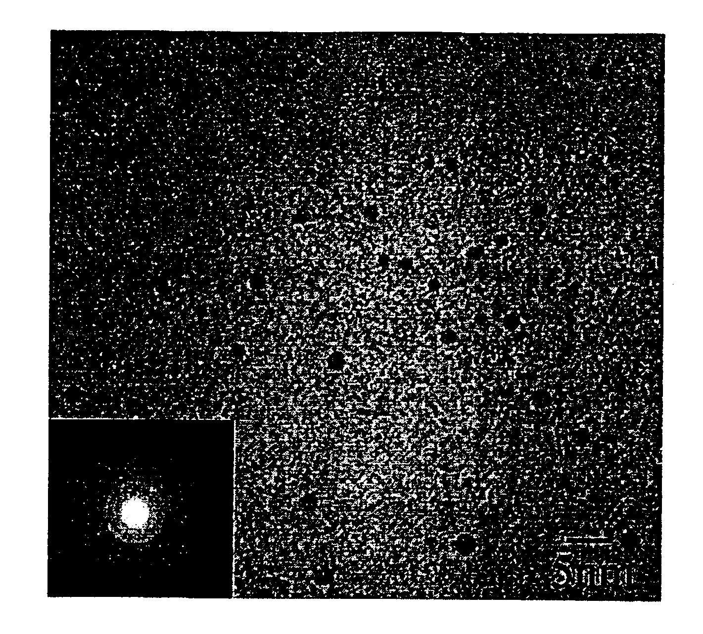
[0061]About 80 ml of distilled water was poured in a reactor of 1 L installed in a thermostat bath set to 25° C. Thereafter, 6 g of decyltrimethylammonium bromide (DTAB) was added and then agitated at the rate of about 400 rpm to form micells. 2 g of pyrrole monomers were slowly dropped in the reactor using a pipette. 11.12 g of FeCl3 (the mole rate of pyrrole / FeCl3=1 / 2.3) were dissolved in 10 ml of distilled water and then the thusly obtained solution was added into the reactor. After agitation for about 4 hours at 25° C., about 500 ml of methanol was added into the reactor to destroy the micells. The reaction solution was moved into a separatory funnel, and then the separatory funnel was smoothly shaken a few times to help blending of the solution. In order to increase the separation rate of the synthesized polymer nano-particle (polypyrrole nano-particle), about 100 ml of iso-octane was added as a non-solvent into the separatory funnel. The upper layer of iso-octane and methanol ...

example 2

[0063]1% by weight, 3% by weight and 10% by weight of the carbon nano-particles with the mean particle diameter of 2 nm, prepared in the example 1, were solution-blended into polycarbonate (average molecule weight: 13,800), respectively. Then, the blend was spin-coated on a cover glass by the thickness of 270 nm (measured by alpha step method) to prepare a film. Tetrahydrofurane (THF) was used as a solvent for the solution blending. For comparison therewith, the non-carbonizing polymer nano-particle (polypyrrole nano-particle), which was not undergone the carbonization process in the Example 1, and the carbon nanotube (from Aldrich company) were respectively solution-blended with polycarbonate to prepare films was measured with UV / VIS spectrophotometer in a visible ray region. Table 1 (below) shows the average of transmittancy based on the wavelength. As shown in Table 1, the carbon nano-particle has a higher average transmittancy than carbon nanotubes. For example, in addition of 1...

example 3

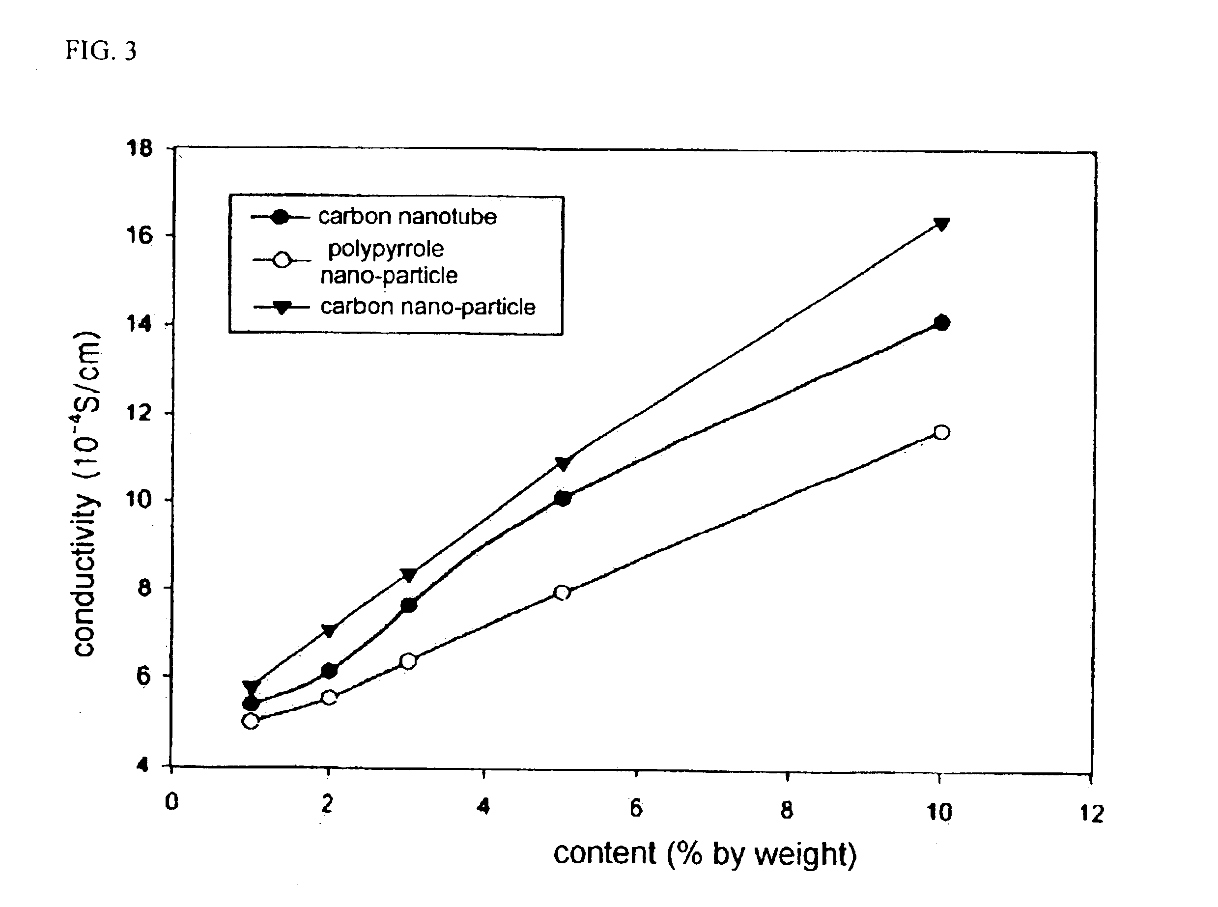
[0065]Specimens were prepared in the same manner as Example 2 except that the polymers nano-particle (polypyrrole nano-particle) and carbon nano-particles and carbon nanotubes were respectively added at 1% by weight, 2% by weight, 3% by weight, 5% by weight, and 10% by weight to make them the pellet shape. The electrical conductivity of the specimens was measured according to the Van der Pauw method. The results of the above measurement are shown in FIG. 3. As shown in FIG. 3, the PC specimens containing the carbon nano-particles according to the present invention had the higher conductivity than any others. For example, in addition of 10% by weight, the PC specimen containing the carbon nano-particle has the electrical conductivity of 16×10−4 s / cm, which shows that the PC specimen containing the carbon nano-particle according to the present invention has the significantly high conductivity, compared to the PC specimen containing the carbon nanotube which has the conductivity of 14×...


PUM

PropertyMeasurementUnit
Temperatureaaaaaaaaaa

Abstract

The present invention relates to a novel carbon nano-particle and a novel method of preparing the same and a transparent, conductive polymer composite containing the same. The carbon nano-particle has the mean diameter of 1 through 50 nm and the shape of sphere, rod or others, which is a novel material not known in the relevant art. Because of a particle size less than ½ of the shortest wavelength of a visible ray, a transparent resin containing the carbon nano-particle can maintain the transparency. Furthermore, the carbon nano-particle has the excellent electric conductivity and the ferromagnetic property, and can be made by a novel, low cost method entirely different from those of fullerene and carbon nanotube.

Description

BACKGROUND OF THE INVENTION[0001]1. Field of the Invention[0002]The present invention relates to a novel carbon nano-particle and a method of preparing the same and a transparent conductive polymer composite containing the same. More particularly, the present invention provide a novel carbon nano-particle in which carbon atoms forming a particle are bound in the graphite structure, and the mean diameter of the particle is 1 through 50 nm, preferably, 1 through 10 nm, and which has the shape of sphere, rod, or other shapes, and a novel method of preparing the carbon nano-particle, and a polymer composite, containing the carbon nano-particle, with the transparency as well as the excellent conductivity, in any case, the ferromagnetism.[0003]2. Description of the Background Art[0004]In recent years, information technology (IT), biotechnology (BT) and nanotechnology (NT) draw an intensive attraction as highly advanced technologies. Of them, the intensive researches in the nanotechnology ...

Claims


Application Information

Patent Timeline
IPC IPC(8): C01B31/00C01B31/02C08K3/04C08K3/00H01B1/24C08J5/18C08L69/00
CPCB82Y10/00B82Y30/00C01B31/02C08K3/04H01B1/24C08K2201/011Y10T428/265Y10S977/773Y10S977/788Y10S977/838Y10T428/29Y10T428/2982Y10S977/742C01B32/05
Inventor JANG, JYONGSIKOH, JOON HAKKIM, DONG CHEOL
Owner DONG WOON INT
Learn More