Skinned hollow fiber membrane and method of manufacture

a hollow fiber and fiber technology, applied in the field of hollow fiber membrane and method of manufacture, can solve the problems of low porosity and depletion of microporous membrane properties, and achieve the effect of not preventing solvent evaporation and preventing the formation of skin

Inactive Publication Date: 2005-07-26
ENTEGRIS INC +1
View PDF38 Cites 14 Cited by
  • Summary
  • Abstract
  • Description
  • Claims
  • Application Information

AI Technical Summary

Benefits of technology

[0019]In the present invention, controlled evaporation of solvent from at least one surface of the hollow fiber as it exits the die tip is combined with higher polymer solids solutions and the submerged extrusion process to produce asymmetric hollow fiber porous membranes, skinned on at least one surface, more specifically, ultrafiltration and contactor membranes, from perfluorinated thermoplastic polymers. It was found that polymer concentrations required to make suitable membranes for the purposes described were from about 12% to about 75%, with preferred concentrations from about 30% to about 60%. Furthermore, in a preferred embodiment in which the skin is formed on the inner surface, the lumen liquid was replaced with a fluid, preferably a gas, that does not prevent solvent evaporation. Without the presence of th

Problems solved by technology

This was deleterious to microporous membrane properties.
It was found that at solutions of

Method used


Image

  • Skinned hollow fiber membrane and method of manufacture
  • Skinned hollow fiber membrane and method of manufacture
  • Skinned hollow fiber membrane and method of manufacture

Examples


example 1

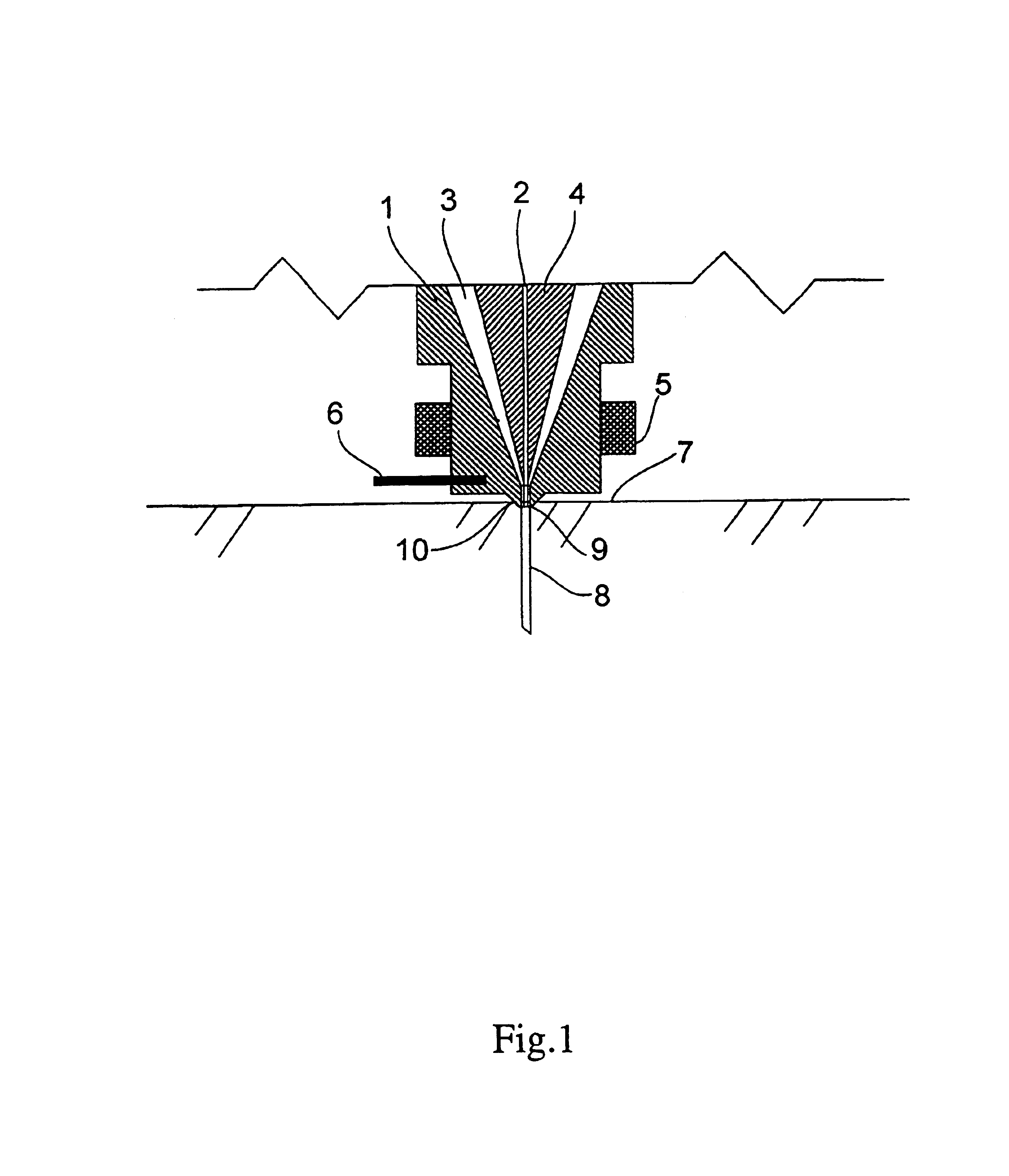
[0073]Hyflon MFA® grade 620 (poly(PTFE-CO-PFVAE)) powder obtained from Ausimont USA, Inc., Thorofare, N.J., was used as received. The powder was mixed with HaloVac® 60 solvent from Halocarbon Oil Inc, River Edge, N.J. to produce a paste of 30% by weight polymer solids. The polymer / solvent paste mixture is introduced into a heated barrel of a twin screw Baker-Perkins (Saginaw, Mich.) extruder having 29 mm screws, by means of a Moyno (Springfield, Ohio)progressive cavity pump. The extruder barrel temperatures were set at between 180° C. and 300° C. A Zenith® melt pump (Waltham, Mass.) was used to meter the melt into the special hollow fiber die mentioned above. The die annulus was approximately 300 microns. A low volume flow controller, Brooks Instrument 8744, (Hatfield, Pa.) fed air at controlled rate to maintain the hollow portion of the fiber. The melt pump and air pressure were adjusted to produce a fiber with about a 150 micron thick wall and a 540 micron diameter lumen at a spin...

example 2

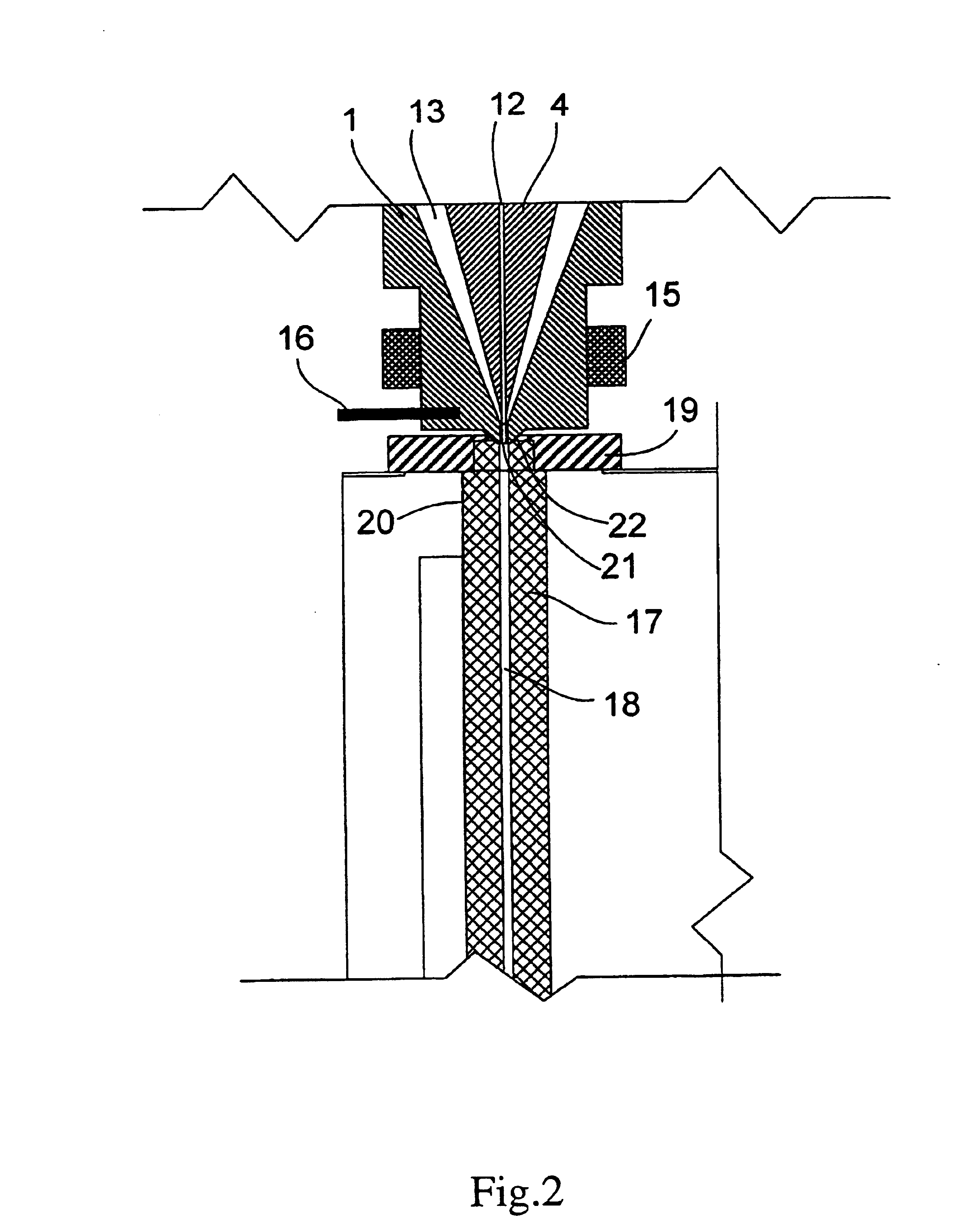
[0075]Pellets of Hyflon MFA® 620(Poly(PTFE-COPFVAE)) obtained from Ausimont USA, Inc., Thorofare, N.J., were ground to about 300 micron size and were mixed with HaloVac® 60 from Halocarbon Oil Inc, River edge, N.J. to produce a paste of 40% by weight polymer solids. The polymer / solvent paste mixture is introduced into a heated barrel of a twin screw Baker-Perkins (Saginaw, Mich.) extrudor having 29 mm screws. The extruder barrel temperatures were set at between 180° C. and 285° C. A Zenith melt pump (Waltham, Mass.) was used to meter the melt into the special hollow fiber die mentioned above. The die annulus was approximately 300 microns. A low volume flow controller. Brooks Instrument 8744, (Hatfield, Pa.) fed air at controlled rate to maintain the hollow portion of the fiber. The melt pump and air pressure were adjusted to produce a fiber with about a 250 micron thick wall and a 540 micron diameter lumen at a spinning rate of 100 feet per minute. Dioctyl pthalate, maintained at 35...

example 3

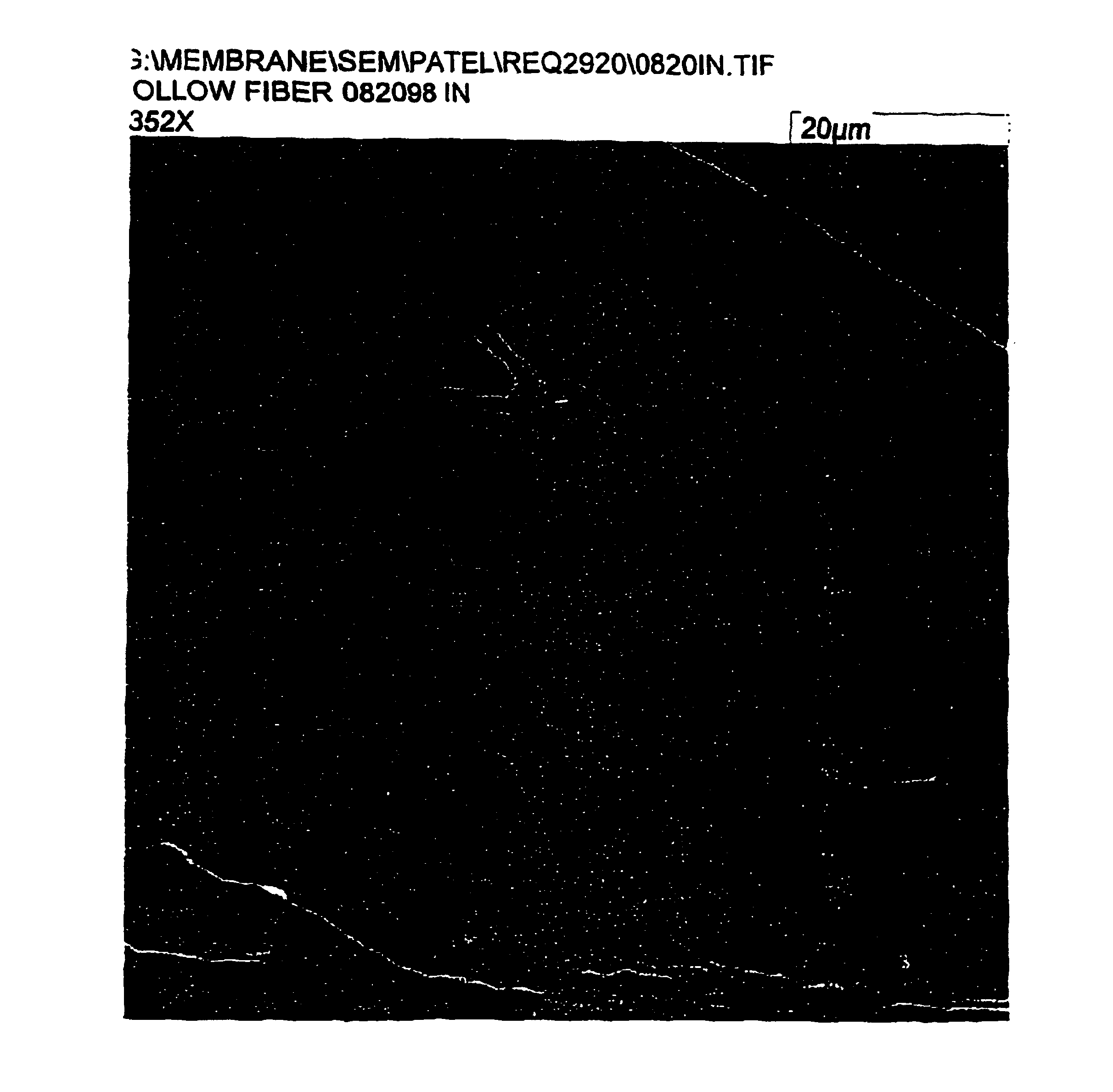
[0076]In this example, water is degassed using a membrane made in a manner similar to the membrane of Example 1. A bundle of fibers was made, potted and installed in a cylindrical holder that separated the lumen side from the shell or outer side of the fibers. The fiber ID was 500μ and the fiber wall was about 150μ The number of fibers was about 500 and the length of the module was about 20 cm. Water, at a temperature of 20° C., was pumped through the fiber lumens and a vacuum of 60 Torr was maintained on the shell side. The oxygen level of the water was measured at the inlet and outlet of the membrane bundle at various flow rates.

[0077]The same module was used for gasification efficiency. In this mode, water at 20° C. was pumped through the lumen just as before, except that the feed water was degassed by a Hoechst Liquid Cel degasser. The shell side was purged with low-pressure air on one end, while the other end was left open. Because of the low gas flow, there was practically no ...


PUM

PropertyMeasurementUnit
Pore sizeaaaaaaaaaa
Pore sizeaaaaaaaaaa
Pressureaaaaaaaaaa

Abstract

Hollow fiber membranes having a skinned surface on one diameter, and a porous surface on the opposite diameter arm produced from perfluorinated thermoplastic polymers by extruding a heated solution of the polymer having a lower critical solution temperature directly into a cooling bath to form the porous membrane by liquid-liquid phase separation. Extrusion can be conducted either vertically or horizontally. The hollow fiber membranes are useful as ultrafiltration membranes and as membrane contactors.

Description

[0001]This application claims the benefit of the filing date of PCT Application PCT / US00 / 02194, filed Jan. 27, 2000 which, in turn, claims the benefit of the filing date of Provisional Application Ser. No. 60 / 117,854, filed Jan. 29, 1999.FIELD OF THE INVENTION[0002]This invention relates to a process to produce asymmetric hollow fiber membranes from perfluorinated thermoplastic polymers, and to the membranes so produced.BACKGROUND OF THE INVENTION[0003]Hollow fiber membranes are used in a wide variety of applications. Ultrafiltration hollow fiber membranes are used to separate proteins and other macromolecules from aqueous solutions. Ultrafiltration membranes are usually rated in terms of the size of the solute they will retain. Typically, ultrafiltration membranes can be produced to retain dissolved or dispersed solutes of from about 1000 Daltons to about 1,000,000 Daltons. They can be rated by Molecular Weight Cutoff, which is the molecular weight expressed in Daltons, a unit of m...

Claims


Application Information

Patent Timeline
IPC IPC(8): B01D67/00B01D71/00B01D69/00B01D71/36B01D69/08D01F6/28D01F6/32D01D5/00D01D5/24
CPCB01D67/003B01D69/08B01D71/36D01D5/24D01F6/32B01D67/0009B01D67/0095B01D2323/22B01D2325/022B01D2325/34
Inventor CHENG, KWOK-SHUNGATES, T. DEANYEN, LARRY Y.PATEL, RAJNIKANT B.
Owner ENTEGRIS INC
Why Eureka
Try Eureka