Superconductor connection structure

a superconductor and connection structure technology, applied in the direction of connection contact material, superconducting magnets/coils, magnetic bodies, etc., can solve the problems of deteriorating superconducting characteristics, complicated steps, complex structure, etc., and achieve the effect of simplifying the structure of the connection point and reducing power consumption

Inactive Publication Date: 2005-07-26
HITACHI LTD
View PDF5 Cites 31 Cited by
  • Summary
  • Abstract
  • Description
  • Claims
  • Application Information

AI Technical Summary

Benefits of technology

[0028]The superconducting magnet apparatus according to claim 12 is characterized by comprising a superconducting line connection method manufactured in the method for producing a superconducting line connection structure according to claim 7. This superconducting magnet apparatus allows a large current to be sent to a connection point, and permits power consumpti

Problems solved by technology

This method, however, involves complicated steps and a complex structure.
Further, critical magnetic field of the metal or alloy is 1 T or less, and the connection point cannot be laid out in high m

Method used


Image

  • Superconductor connection structure
  • Superconductor connection structure
  • Superconductor connection structure

Examples


embodiment 1

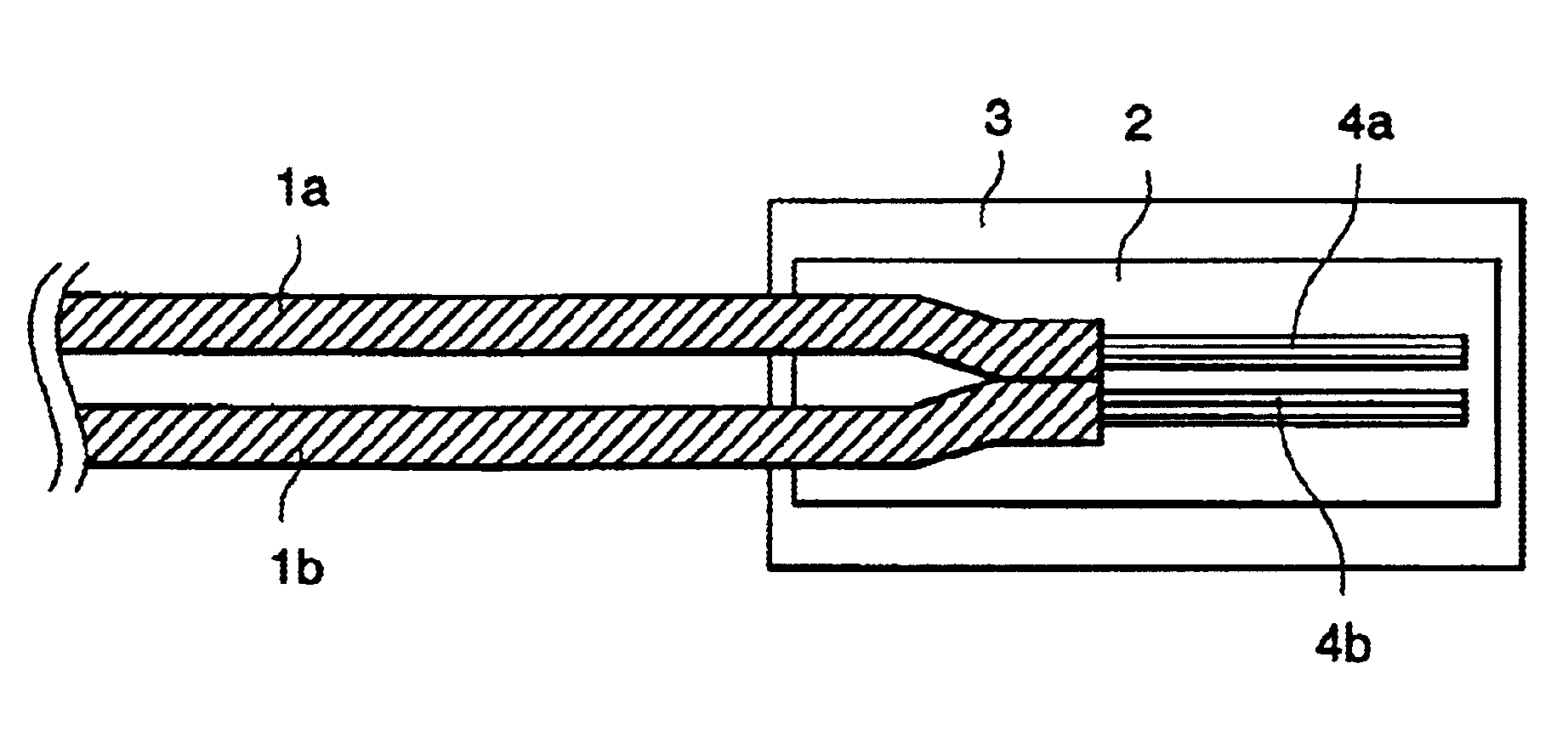
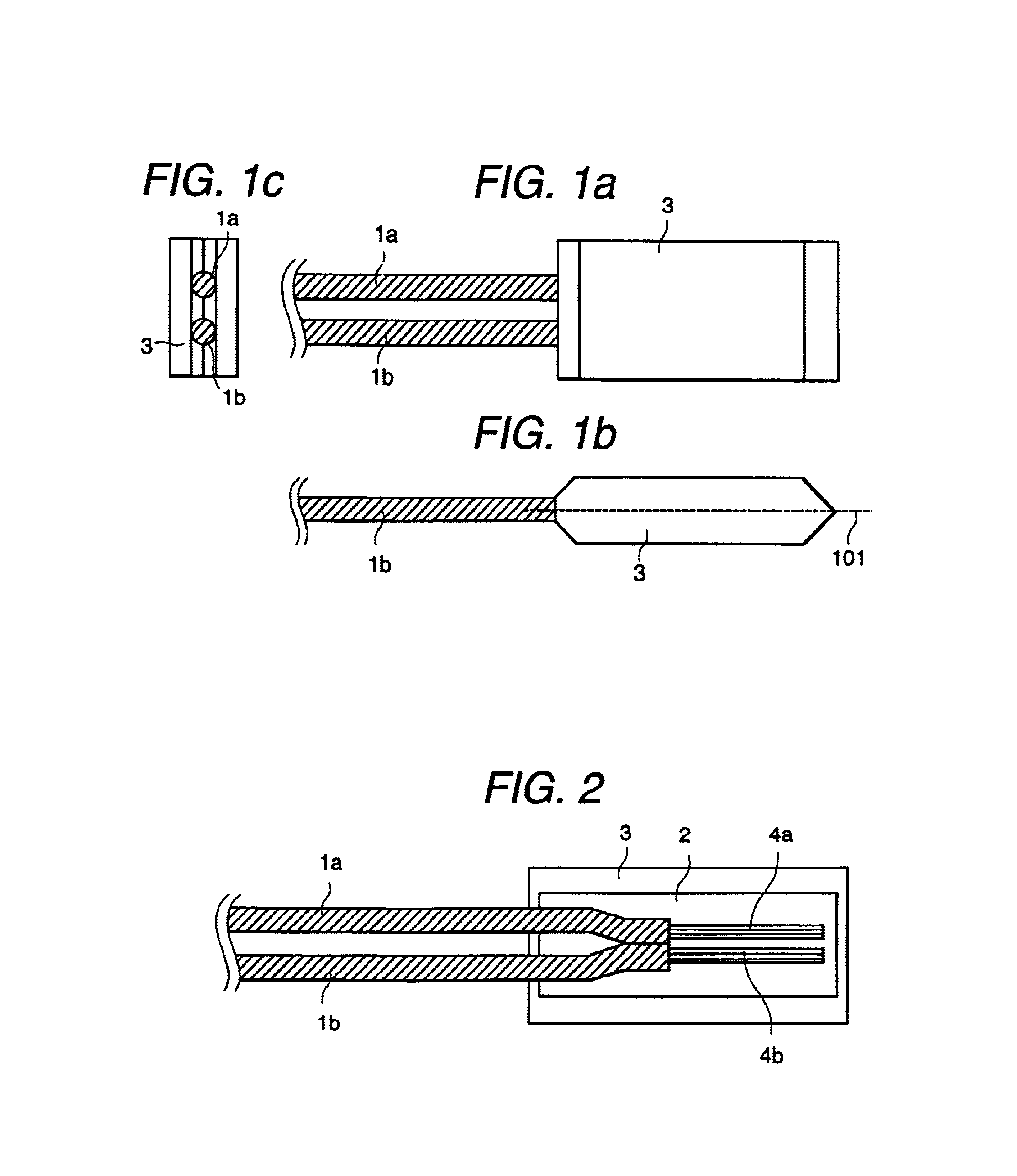
[0044]FIGS. 1a to 1c are external views in the first embodiment of a superconducting line connection (hereinafter referred to as “connection point”) according to the present invention. FIG. 2 is a cross sectional view representing the interior of the first embodiment according to the present invention. FIG. 2 is a cross sectional view of the connection point taken along a line 101 in FIG. 1b.

[0045]The following describes the structure of the connection point.

[0046]Reference numerals 1a and 1b denote superconducting lines to be connected.

[0047]The superconducting lines 1a and 1b are multi-filament superconducting lines where niobium titanium (NbTi) is used as a superconducting material and anoxic copper is employed as a stabilizer. An NbTi superconducting line was used in the present embodiment, but other superconducting lines may be used. The stabilizer was removed from superconducting lines 1a and 1b, and superconducting filaments 4a and 4b are exposed inside the connection point....

embodiment 2

[0054]MgB2 powder with varying average particle sizes was prepared in advance, and a connection point was manufactured in the same method as Embodiment 1. The average particle size was measured by a scanning electron microscope, and the particle size of 95% or more powder was confirmed to be within 20% of the average particle size. MgB2 powder is compressed to the density equivalent to 80%±5% of the theoretical density. Table 1 shows the relationship between the result of measuring the critical current of the connection produced in this way and the average particle size. Unless otherwise specified, it is assumed that anoxic copper is used for the coating material of the connection point, and the NbTi line described in Embodiment 1 is used for the superconducting line.

[0055]

TABLE 1Average particle8111417202326293235size (μm)Critical current490440480460450350340310280210(A)

[0056]As shown in Table 1, when the average particle size is 20 microns or more, the critical current tends to in...

embodiment 3

[0057]Using the pipe made of gold, silver, copper, platinum, palladium, aluminum, niobium, lead, tin, magnesium, indium, tungsten, cobalt, nickel, iron, tantalum or chromium, the present inventors produced connection points according to the method as in Embodiment 1. It has been revealed that connection in the superconducting state is possible for all types. Especially copper, gold, silver and aluminum have excellent spreading property; therefore, when the pipe was crimped, excellent correction structure was obtained without any crack on the surface. Connection points were produced using the pipes made of SUS304 stainless steel, copper / nickel alloy, silver / magnesium alloy and the like, and it has been revealed that connection in the superconducting state is possible.


PUM

PropertyMeasurementUnit
Fractionaaaaaaaaaa
Particle sizeaaaaaaaaaa
Volumeaaaaaaaaaa

Abstract

Electrical connection of superconducting lines can be achieved by using a low-melting point metal, by mechanical contact of superconducting lines or by welding. According to these methods, however, critical current and critical magnetic field at the connection point are low, and stable connection in a superconducting state has been difficult. The present invention solves these problems and provides a structure and method for connecting superconducting lines. The present invention provides high-performance, high-stability connection of superconducting lines through magnesium diboride (MgB2) powder arranged between superconducting lines.

Description

BACKGROUND OF THE INVENTION[0001]1. Field of the Invention[0002]The present invention relates to a superconducting line, superconducting line connection structure and production method thereof. To put it more specifically, the present invention applies to a superconducting magnet system, current lead, power transmission cable, nuclear magnetic resonance analyzer, magnetic resonance diagnostic apparatus for medical use, superconducting power storage apparatus, magnetic separation apparatus, single crystal pulling apparatus in magnetic field, refrigerator cooling superconducting magnet apparatus, superconducting energy storage, superconducting generator and magnet for nuclear fusion reactor.[0003]2. Description of Prior Art[0004]A superconducting magnet apparatus, superconducting power cable or the like may require electrical connection of two or more superconducting lines. For example, electric resistance at a connection point must be minimized in the permanent current operated super...

Claims


Application Information

Patent Timeline
IPC IPC(8): H01L39/02H01R4/58H01R4/68H01F6/06H01B12/02H01B13/00
CPCH01L39/02H01R4/68Y10T29/49014H10N60/80
Inventor MORITA, HIROSHITANAKA, KAZUHIDESUZUKI, YASUOOKADA, MICHIYA
Owner HITACHI LTD
Why Eureka
Try Eureka