Crystal manufacture method

a manufacturing method and crystal technology, applied in the field of crystal manufacture methods and apparatuses, can solve the problems of unsatisfactory optical characteristics of short-wavelength and high-power light such as excimer lasers, low laser durability, large homogeneity and birefringence of refractive indexes, etc., and achieve excellent optical characteristics.

Inactive Publication Date: 2005-08-16
CANON KK
View PDF4 Cites 13 Cited by
  • Summary
  • Abstract
  • Description
  • Claims
  • Application Information

AI Technical Summary

Benefits of technology

[0017]Another specific and exemplary object of the present invention is to provide calcium fluoride crystal having excellent optical characteristics including the laser durability, and its manufacturing method.
[0019]Still another exemplary object of the present invention is to provide a device manufacture method using the exposure apparatus and high quality devices (such as semiconductors, LCDs, CCDs, thin magnetic heads) fabricated using the exposure apparatus.

Problems solved by technology

However, the CaF2 crystal manufactured by the conventional manufacture methods exhibit satisfactory optical characteristics for visible light, but has a disadvantage in that it has not yet exhibited satisfactory optical characteristics for short-wavelength and high-power light such as excimer laser, e.g., low laser durability, large refractive index homogeneity and birefringence, poor surface precision at the time of grinding process, etc.
As a result that the instant inventor has eagerly studied the causes, he has found that it results from the crystal or lattice defect or dross inclusion.
However, the crystal for use with the excimer laser has such a large aperture that it has a difficulty in one-way crystallization and cannot sufficiently remove impurities disadvantageously.
As a result, impurities, such as rare earth, and bubbles concentrate in the middle of crystal, which is a part finally solidified, and are hard to be removed.

Method used


Image

  • Crystal manufacture method
  • Crystal manufacture method
  • Crystal manufacture method

Examples


first example

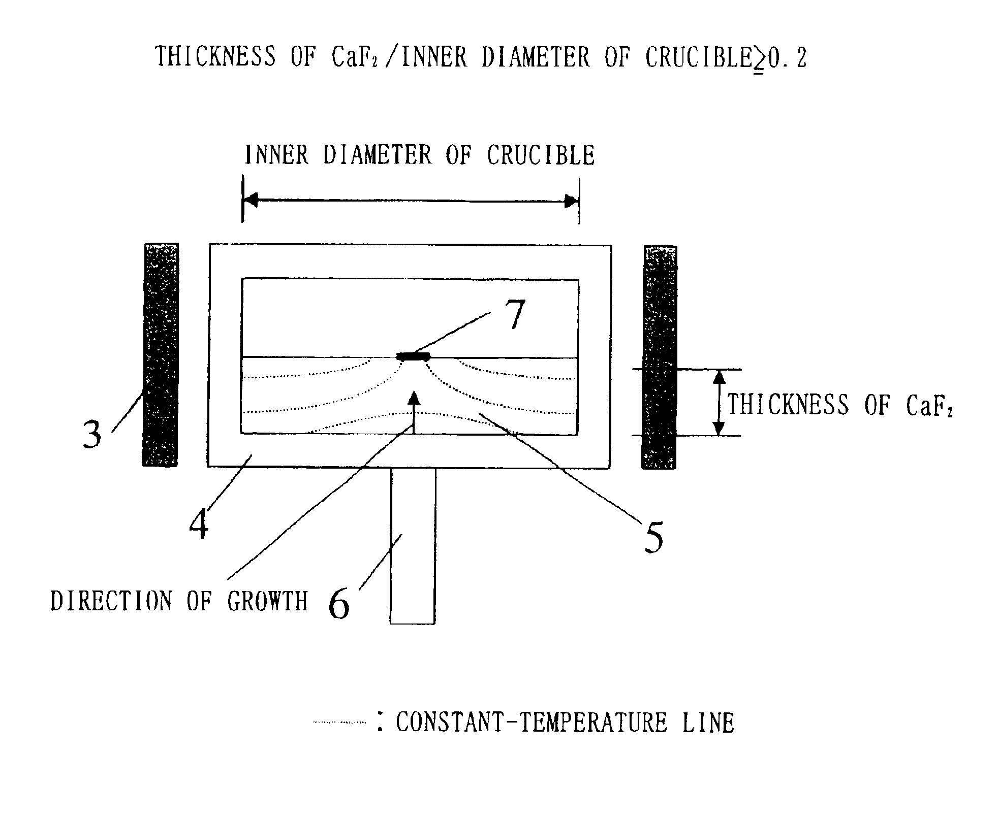
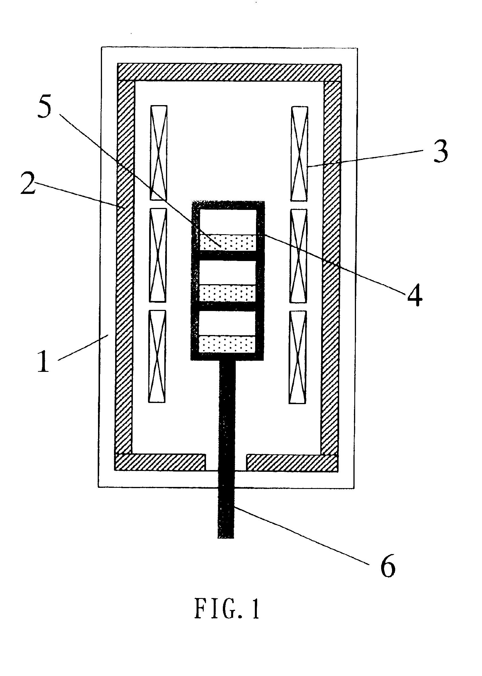
[0044]Zinc fluoride was added as scavenger and mixed with the calcium fluoride material by about 0.076 mol %. Then, this mixture was put in the multistage crucible having a bore of 250 mm and a depth of 150 mm in a purification furnace shown in FIG. 1 and the furnace was exhausted. Then, the crucible was heated up to 1420° C. and the material was melted. The crucible was then descended at a speed of 20 mm / h and cooled gradually, and the material was crystallized. The crystallized block size was a diameter of 250 mm and a thickness of 50 mm. Air bubbles, etc. concentrated at the top of the crystal, and thus good crystal was obtained.

[0045]Next, the above crystal block was put in the crucible for single crystal growth shown in FIG. 5. The furnace was vacuum-exhausted, and the temperature was maintained to be 1420° C. for 30 hours. Then, the crucible for growth was descended at a speed of 1 mm / h.

[0046]Then, the grown calcium fluoride single crystal and zinc fluoride of 0.1 weight % wer...

second example

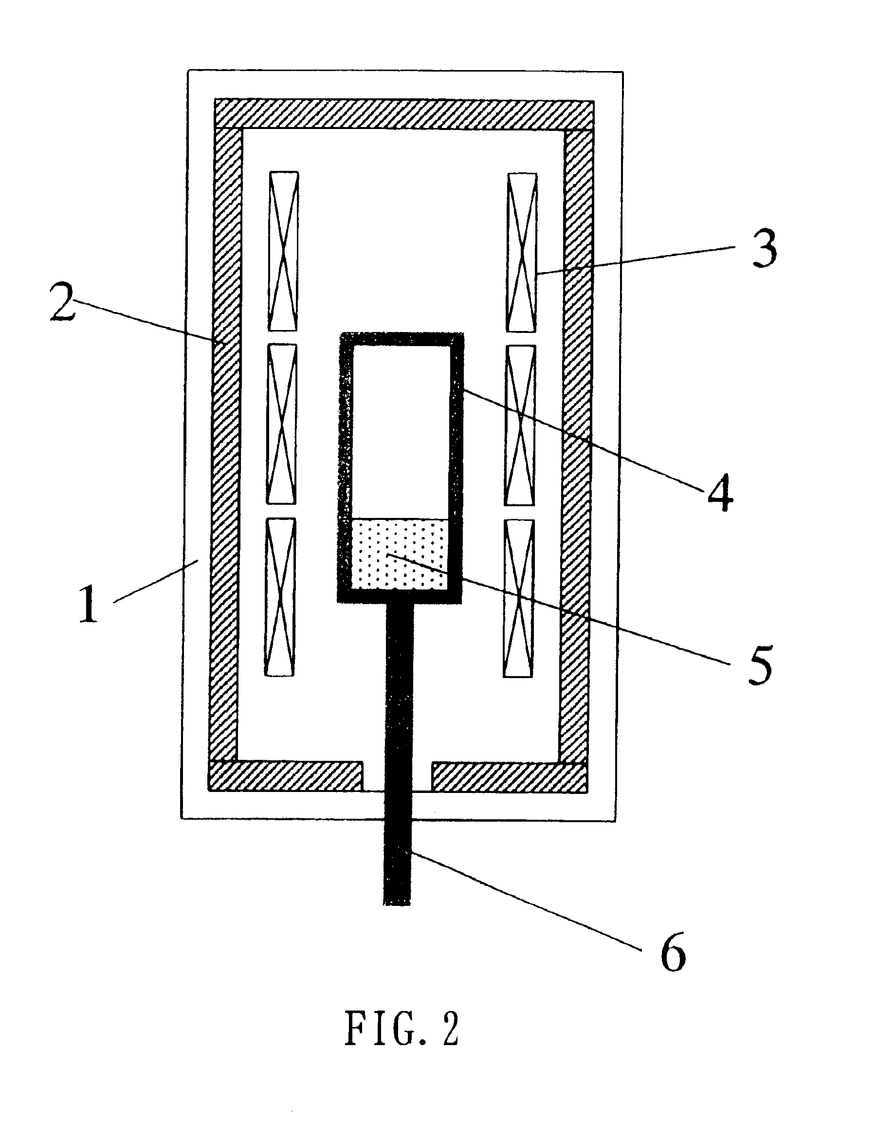
[0047]This example is the same as the first example except for including the steps of cutting, after the material was purified using one stage of crucible having a depth shown in FIG. 2, the top and bottom surfaces accumulating impurities, and processing so that it may have a size that facilitates installation into the growth furnace. Calcium fluoride thus obtained had excellent transmittance and remarkably little deterioration.

[0048]The present invention may provide calcium fluoride crystal having excellent optical characteristics, and its manufacture method and apparatus. An optical element made of such calcium fluoride crystal is applicable to an optical system in an exposure apparatus for fabricating high-quality devices through exposure with high resolution and throughput.


PUM

PropertyMeasurementUnit
inner diameteraaaaaaaaaa
wavelengthaaaaaaaaaa

Abstract

A method for manufacturing fluoride crystal includes the steps of adding scavenger and a material to a crucible, melting the scavenger and material at a temperature higher than a melting point so that a ratio of a thickness of the fluoride crystal that has been melted to an inner diameter of the crucible may be 0.2 or higher, and gradually crystallizing and purifying the material.

Description

BACKGROUND OF THE INVENTION[0001]The present invention relates generally to crystal manufacture methods and apparatuses, and more particularly to a manufacture method for calcium fluoride (CaF2) crystal usable as a material for optical elements used for an exposure apparatus for photolithography.[0002]Along with the recent demands on smaller and thinner-profile electronic devices, finer semiconductor devices to be mounted onto these electronic devices have been increasingly demanded. For example, a design rule for a mask pattern tries to achieve a line and space (L & S) of 130 nm on a mass production line, and predictably it will be increasingly smaller in the future. L & S denotes an image projected to a wafer in exposure with equal line and space widths, and serves as an index of exposure resolution.[0003]The exposure has three important parameters, i.e., resolution, overlay accuracy and throughput. The resolution is a minimum size for a precise pattern transfer. The overlay accur...

Claims


Application Information

Patent Timeline
Patent Type & Authority Patents(United States)
IPC IPC(8): C30B11/00C01F11/22C30B29/12G02B1/02G02B3/00
CPCC30B11/00C30B29/12
Inventor DOGUCHI, KENTARO
Owner CANON KK
Why Eureka
Try Eureka