Methods of conducting simultaneous exothermic and endothermic reactions

a technology of exothermic and endothermic reactions and reactors, which is applied in the direction of chemical/physical/physico-chemical stationary reactors, chemical/physical/physical-chemical production, and final product manufacturing, etc., can solve the problems of less effective use of channels having a minimum dimension of more than 2 mm, and achieve good yield, reduce contact time, and good performance

Inactive Publication Date: 2005-11-29
BATTELLE MEMORIAL INST
View PDF45 Cites 87 Cited by
  • Summary
  • Abstract
  • Description
  • Claims
  • Application Information

AI Technical Summary

Benefits of technology

[0069]Another advantage of the present invention is that good yields (or other measures of good performance) can be obtained with short contact times. In preferred methods, the contact time is less than 100 milliseconds (ms), more preferably less than 50 ms and still more preferably between 1 and 25 ms for gas phase reactions. Liquid phase reactions would be expected to be at least three orders of magnitude slower. Contact time may be reduced by reducing the diffusion distance between the bulk flow and the porous catalyst while concurrently reducing channel length. At these contact times, in a preferred embodiment of hydrocarbon steam reforming, at least 70%, more preferably at least 90%, of the equilibrium conversion of the hydrocarbon entering the beginning of said at least one reaction chamber is converted to hydrogen, carbon monoxide and/or carbon dioxide. Similar improvements can be obtained in other processes.
[0075]5. Optional: quench/inhibit gas phase reactions. As the channel dimension nears the quench diameter or drops below, then the contribution of the unwanted gas phase homogeneous combustion reaction is reduced.
[0076]In its broader aspect

Problems solved by technology

The use of channels having a minimum dimension of more than 2 mm may be

Method used


Image

  • Methods of conducting simultaneous exothermic and endothermic reactions
  • Methods of conducting simultaneous exothermic and endothermic reactions
  • Methods of conducting simultaneous exothermic and endothermic reactions

Examples


example 1

Integrated Combustor Reactor (ICR)

[0085]This integrated catalytic combustor reactor was composed of a single methane steam reformer channel that shares a wall with a single catalytic combustion channel. Heat was transferred through this common wall from the hot (combustion) side to the cold (reforming reaction) side to drive the endothermic reaction. One design (version 1) of the ICR had no header or footer space for the combustion stream, instead introducing the unmixed combustion gases directly onto the catalyst. This was done to insure that homogeneous combustion did not occur upstream of the catalyst (i.e. in the header). A second design of the ICR (version 2) was fabricated which included a 0.25″ (6.4 mm) by 0.4″(10.2 mm) header and footer space on the combustion side, identical to those on the reformer side (see FIG. 8). This was done to reduce the likelihood of channeling on the combustor side and to more evenly distribute the flow (and thus the heat of reaction) over the ent...

example 2

[0105]This example describes the design, fabrication, and test results from a high efficiency, high-throughput small microchannel reactor in which heat producing (exothermic) and heat consuming (endothermic) reaction channels are immediately adjacent (integrated). Combustion of hydrogen in air was used as the exothermic reaction, while steam reforming of methane with a steam to carbon ratio of 3:1 was used as the endothermic reaction. A new ICR design (flow-by) was used which allowed for much higher throughput with minimal (i.e. <11 psi) pressure drop by allowing each reactant stream to flow in a narrow (0.125 mm) gap adjacent to the porous engineered catalyst. The new design included a central combustion zone (of two microchannels) flanked by a reformer channel on either side.

[0106]The ICR (see FIG. 13) used a shortened combustion catalyst bed (0.2″, 0.5 cm) to allow a combination of catalytic and homogenous hydrogen combustion. Hydrogen was only distributed across the channel widt...

example 3

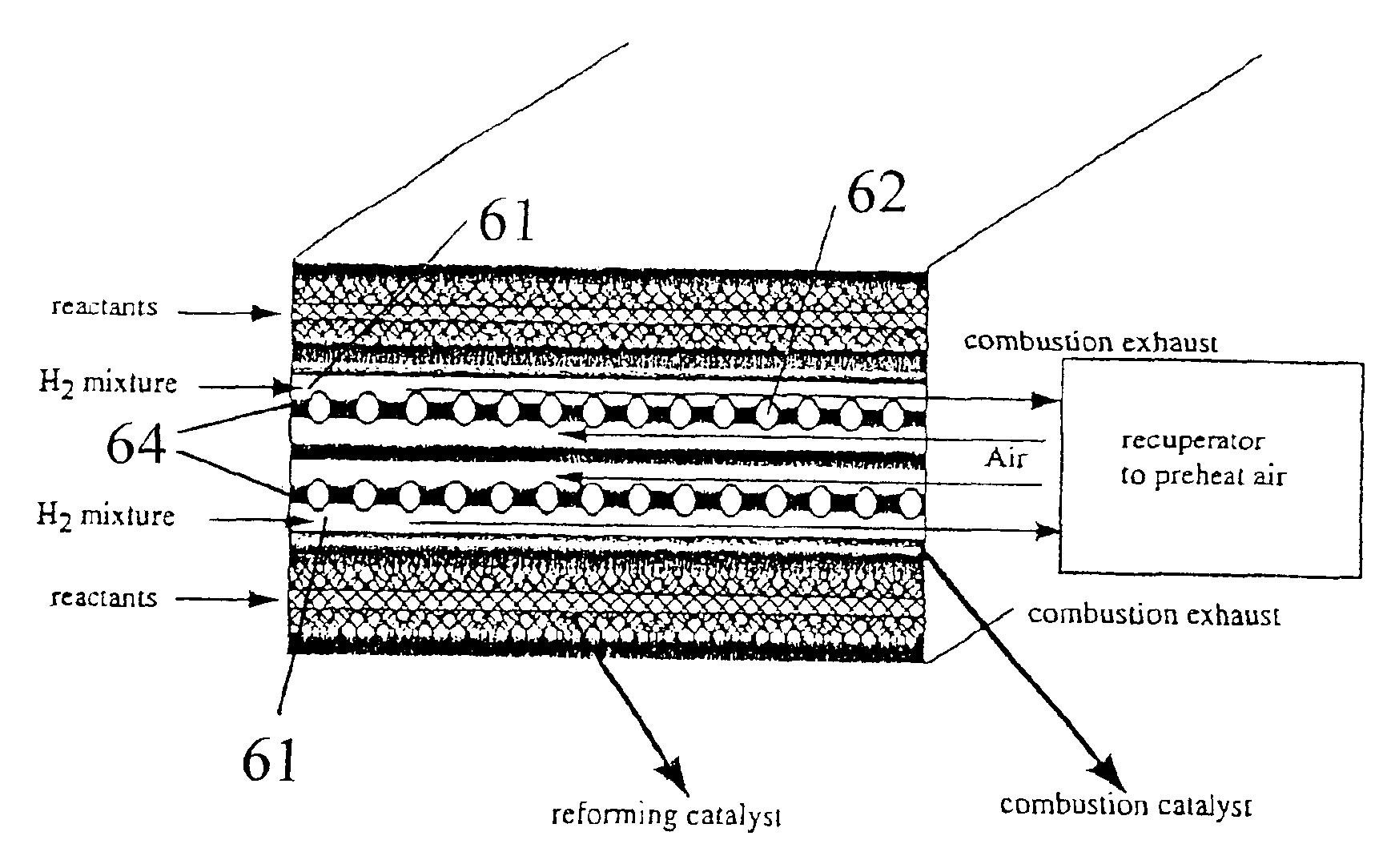
[0120]This example describes the design and testing of a multichannel interleaved microchannel reactor in which heat producing (exothermic) and heat consuming (endothermic) reaction channels are interleaved (integrated) with each other. Combustion of hydrogen in air was used as the exothermic reaction, while steam reforming of methane with a steam to carbon ratio of 2:1 was used as the endothermic reaction. The pressure for both reactions was near atmospheric and operated at a pressure required to overcome the system pressure drop. For the SMR side, the typical operating pressure was 139 kPa (5.5 psig) and for the combustion side the typical operating pressure was also 137 kPa (5.2 psig). A flow-by design (flow-by) was used which allowed for much higher throughput with minimal (<0.2 bar, or 3 psid) pressure drop by allowing the reactant stream in each channel (whether exothermic or endothermic) to flow in a narrow (about 0.2 mm) gap between two layers of porous engineered catalysts ...


PUM

PropertyMeasurementUnit
Lengthaaaaaaaaaa
Fractionaaaaaaaaaa
Fractionaaaaaaaaaa

Abstract

Integrated Combustion Reactors (ICRs) and methods of making ICRs are described in which combustion chambers (or channels) are in direct thermal contact to reaction chambers for an endothermic reaction. Superior results were achieved for combustion chambers which contained a gap for free flow through the chamber. Particular reactor designs are also described. Processes of conducting reactions in integrated combustion reactors are described and results presented. Some of these processes are characterized by unexpected and superior results.

Description

RELATED APPLICATIONS[0001]This application is a continuation-in-part of U.S. patent application Ser. No. 09 / 375,614 filed Aug. 17, 1999, now U.S. Pat. No. 6,488,838 and Ser. No. 09 / 640,903, filed Aug. 17, 2000 now U.S. Pat. No. 6,680,044, which are incorporated herein as if reproduced in full below. In accordance with 35 U.S.C. sect. 119(e), this application claims priority to U.S. Provisional Application No. 60 / 269,628, filed Feb. 16, 2001.FIELD OF THE INVENTION[0002]The present invention relates to integrated reactors for conducting exothermic and endothermic reactions, methods of making integrated reactors, and methods of conducting reactions in integrated reactors.INTRODUCTION[0003]Currently, endothermic reactions performed in microreactors are driven using heat from an external source, such as the effluent from an external combustor. In doing so, the temperature of the gas stream providing the heat is limited by constraints imposed by the materials of construction. For example,...

Claims


Application Information

Patent Timeline
IPC IPC(8): B01J8/02B01J12/00B01J19/00B01J19/24C01B3/38C01B3/50C01B13/02F23C13/00H01M8/06
CPCB01J12/007B01J19/0093B01J19/249C01B3/38C01B3/384C01B3/501C01B13/0251F23C13/00B01J8/0285F23N1/007B01J2208/00309B01J2219/00783B01J2219/00822B01J2219/00824B01J2219/00833B01J2219/00835B01J2219/00844B01J2219/0086B01J2219/00873B01J2219/00891B01J2219/2453B01J2219/2458B01J2219/2459B01J2219/2465B01J2219/247B01J2219/2471B01J2219/2474B01J2219/2475B01J2219/2479B01J2219/2482B01J2219/2497B01J2219/2498C01B2203/0233C01B2203/0244C01B2203/0261C01B2203/0283C01B2203/041C01B2203/0495C01B2203/0811C01B2203/0822C01B2203/0827C01B2203/0833C01B2203/0844C01B2203/0883C01B2203/1005C01B2203/1029C01B2203/1035C01B2203/1041C01B2203/1064C01B2203/1076C01B2203/1082C01B2203/1205C01B2203/1241C01B2203/1276C01B2203/1288C01B2203/141C01B2203/142C01B2203/148C01B2203/1604C01B2203/1619C01B2203/1633C01B2203/1652C01B2203/1676C01B2203/169C01B2203/1695C01B2203/82H01M8/0631Y10T29/49826Y02E60/50Y02P20/10Y02P20/52Y02P70/50B01J19/24Y02E60/32
Inventor TONKOVICH, ANNA LEEROBERTS, GARY L.PERRY, STEVEN T.FITZGERALD, SEAN P.
Owner BATTELLE MEMORIAL INST
Why Eureka
Try Eureka