
Wide-field extended-depth doubly telecentric catadioptric optical system for digital imaging

a catadioptric optical system and wide field technology, applied in the field of automatic imaging optical systems, can solve the problems of only being able to correct the distortion of the optical system, applying some types of optical systems, and exhibiting substantial distortion that increases, etc., to achieve constant magnification and resolution, wide field of view

Inactive Publication Date: 2005-12-27
LOCKHEED MARTIN CORP
View PDF25 Cites 11 Cited by
  • Summary
  • Abstract
  • Description
  • Claims
  • Application Information

AI Technical Summary

Benefits of technology

The present invention provides an optical system that can capture well-focused images over a wide range of focus and object to lens distances with constant magnification and resolution. This optical system does not require software modification to correct for variable resolution and perspective distortion such as keystone distortions. It also improves performance and throughput of machine vision controlled systems. Additionally, the invention provides an optical system for package and article imaging, and a sorting method for articles with visible information on a face.

Problems solved by technology

However, application of some types of optical systems to purposes in which they might be otherwise advantageous may be precluded by corresponding constraints.
As a simple example, large fields of view must generally be provided by wide-angle lenses which characteristically exhibit substantial distortion that increases with off-axis angle.
Correction of such distortion is often only possible with expensive aspheric elements or through the use of image processing which is expensive.
Long focal length lenses at considerable distances from an object to be imaged have been used to restrict the relative change in resolution over a large change in object position along the optical axis but this can be impractical where space is a limitation and may require the use of multiple path-folding mirrors of high optical quality which are expensive and ultimately reduce overall image quality because of surface irregularities.
This is, at best, only a partial solution since the resolution will still be relatively high at relatively closer object positions thus limiting unnecessarily the ultimate scan rate of the image capture device.
Therefore, some types of lens systems exhibiting some potentially useful properties have little or no known practical application and are often, at most, of theoretical interest.
However, telecentric optical systems, in practice, fall into two groups and a combination or hybrid group, each having a combination of severe constraints.
However, the property of a constant size image is lost if the system is refocused in accordance with such axial motion.
Further, the system must be recalibrated if it is refocused to closer distances than infinity (which will also reduce usable depth of field, referred to therein as a range of sharpness).
However, motion of the object along the optical axis results in a change of magnification of the image, focused or unfocused.
In essence, an image telecentric lens system has virtually no advantages over an object telecentric lens system and significant further constraints.
Even though known measurement applications use telecentric lens systems at a single focus distance, this may be a critical constraint in regard to some possible applications and further limits use of object and image telecentric lenses in applications where a focused image is of importance.
However, it has generally been considered that a doubly telecentric system would be constrained by the constraints characteristic of both object and image telecentric optical systems, especially by the constraint in the field width due to limited width of the object-side objective which is traditionally a refractive lens.
Accordingly, little, if any, practical application has been envisioned for doubly telecentric optical systems.
It is also significant that while object telecentric and image telecentric refractive lenses are commercially available, at least in small diameters, doubly telecentric lenses are not similarly available and cannot reasonably be assembled from commercially available object and image telecentric systems.
The above-incorporated article also acknowledges that the large lens sizes required by telecentric optical systems can be extremely expensive since the cost of a lens generally increases as the cube of the diameter.
Therefore, while the article acknowledges that image processing by computer is complex and slow, particularly in correcting for distortions of non-telecentric lenses used for making optical measurements, such image processing has been more economical than use of large telecentric optical systems which do not change magnification with lens to object distance, at least for measurement applications.
This characteristic of most lenses presents a problem in regard to optical character recognition (OCR), bar code readers (BCRs), feature extraction systems and the like which must also operate from data representing a reasonably well-focused image (e.g. systems which compare image features with templates).
Similarly, optical metrology, requires constant image magnification even where the distance between the object of interest and the optical system may not be well-controlled.
Magnification variation with depth / distance also causes severe perspective distortion (particularly when providing wide angles of view) which present severe difficulties for machine vision systems such as vision based guidance systems and robotics.
Further, as OCR and optical metrology techniques are applied to high throughput systems such as mail sorting, the digital image processing overhead to correct for change of magnification with distance and distortion becomes a major limitation on overall system capacity, even when very high speed digital data processors are employed.
Such image processing necessarily carries a substantial computational overhead to achieve the effect of essentially discarding data and the resolution that data represents and which could otherwise be utilized to improve machine vision system performance.
Additionally, this limitation on throughput carries a significant economic cost in regard to the controlled system which must increasingly be balanced against optical system cost when high throughput is required.
Likewise, image telecentric systems can only be focused at a constant image size by movement of the image plane whereas traditional focusing techniques move either the entire lens or subgroups of elements necessitating movement of the object-side objective in synchrony with the image-side objective.
However, any change in object position relative to the objective changes image magnification.
This difficulty of focusing even image telecentric systems without changing the magnification is thus seen to be a severe limitation on applicability of telecentric optical systems to environments where well-focused images are required.

Method used


Image

  • Wide-field extended-depth doubly telecentric catadioptric optical system for digital imaging
  • Wide-field extended-depth doubly telecentric catadioptric optical system for digital imaging
  • Wide-field extended-depth doubly telecentric catadioptric optical system for digital imaging

Examples


Embodiment Construction

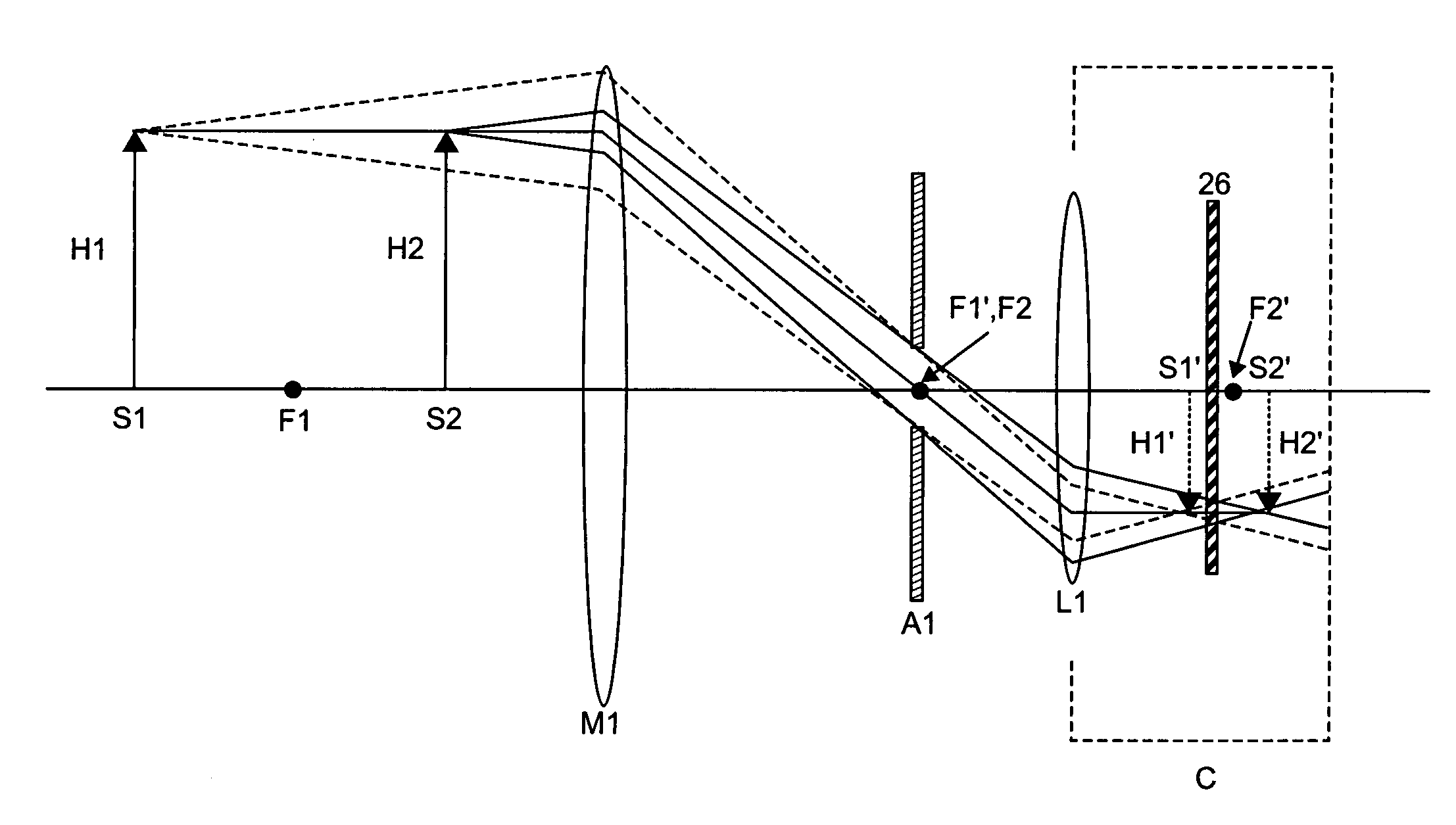
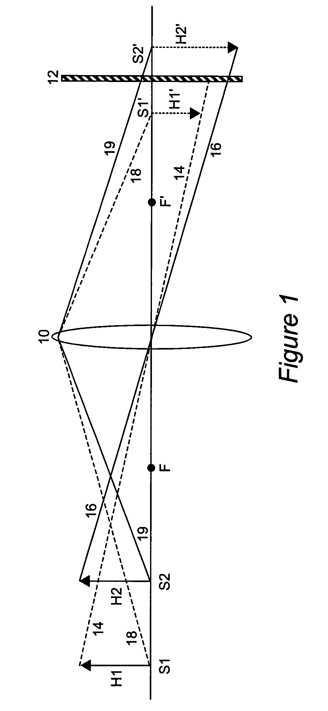
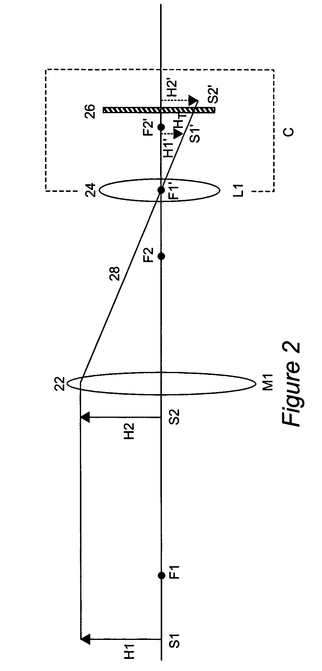
[0037]Referring now to the drawings, and more particularly to FIG. 1, there is schematically shown a conventional lens system 10, having front and rear focal points F, F′, imaging objects H1, H2 of the same size at different locations S1, S2 which are different axial distances from lens 10. It is understood that H1 and H2 can be representations of the same object positioned at different depths along the optical axis and are shown simultaneously for purposes of comparison. They could also represent two points on a hollow object that are axially separated but of the same height. By following the principal rays from the upper ends of the objects H1, H2 it is seen that the image H1′ of object H1 at location S1 at the greater of the two axial distances is focused at location S1′ a short distance behind rear focal point F′. By similarly following the illustrated principal ray from the upper end of object H2, it can be seen that image H2′ is focused at a greater distance behind rear focal ...


PUM


Abstract

Focused imaging of constant size and resolution over a wide range of distances and a wide field of view in object space is provided by a doubly telecentric catadioptric optical system including an external limiting aperture at the juncture of the focal planes of two objectives, with a large-diameter concave spherical or aspheric mirror as the primary objective, and a camera lens as the secondary objective. Constant resolution avoids rescaling of images made at different depths for machine recognition tasks such as OCR, saving computation time and cost, and increasing through-put and accuracy. For digital linescan cameras, constant resolution of the image avoids scanning objects at different line rates for different depths of objects being scanned, thus maximizing speed of the objects and, hence, throughput. The field of view is constant over the entire range of depth and is not limited by the diameter of the camera lens elements. Undesirable cropping of the image of objects close to the imaging system is prevented. The effective f / number of the system is constant over the entire range of focus, and the image irradiance is more uniform over the entire field of view than with a traditional non-telecentric camera lens.

Description

CROSS-REFERENCE TO RELATED APPLICATION[0001]This application claims priority to U.S. Provisional Application Ser. No. 60 / 198,764, filed Apr. 21, 2000, the entire contents of which are hereby incorporated by reference herein.BACKGROUND OF THE INVENTION[0002]1. Field of the Invention[0003]The present invention generally relates to optical systems for automated imaging and, more particularly, to optical systems for digital imaging for optical character recognition (OCR), automated inspection, optical metrology (e.g. object identification and classification), machine vision, robotics, bar code readers (BCRs) and the like.[0004]2. Description of the Prior Art[0005]Many different types of optical systems including one or more lenses and / or mirrors and structure to maintain or adjust the relative positions of such optical elements have been known for many years for various applications, including telescopes, microscopes and human vision correction. Cameras generally combine such optical sy...

Claims


Application Information

Patent Timeline
Patent Type & Authority Patents(United States)
IPC IPC(8): G02B17/08
CPCG02B17/08G01J1/0411
Inventor ALBERTELLI, LAWRENCE E.
Owner LOCKHEED MARTIN CORP
Learn More