
Single vessel multi-zone wastewater bio-treatment system

a bio-treatment system and single-vessel technology, applied in biological water/sewage treatment, filtration separation, separation processes, etc., can solve the problems of increased oxygen demand in the receiving stream, depressed dissolved oxygen concentration, and affecting the processing efficiency of wastewater, so as to achieve better wastewater treatment

Active Publication Date: 2006-03-07
KASPARIAN ANN
View PDF1 Cites 58 Cited by
  • Summary
  • Abstract
  • Description
  • Claims
  • Application Information

AI Technical Summary

Benefits of technology

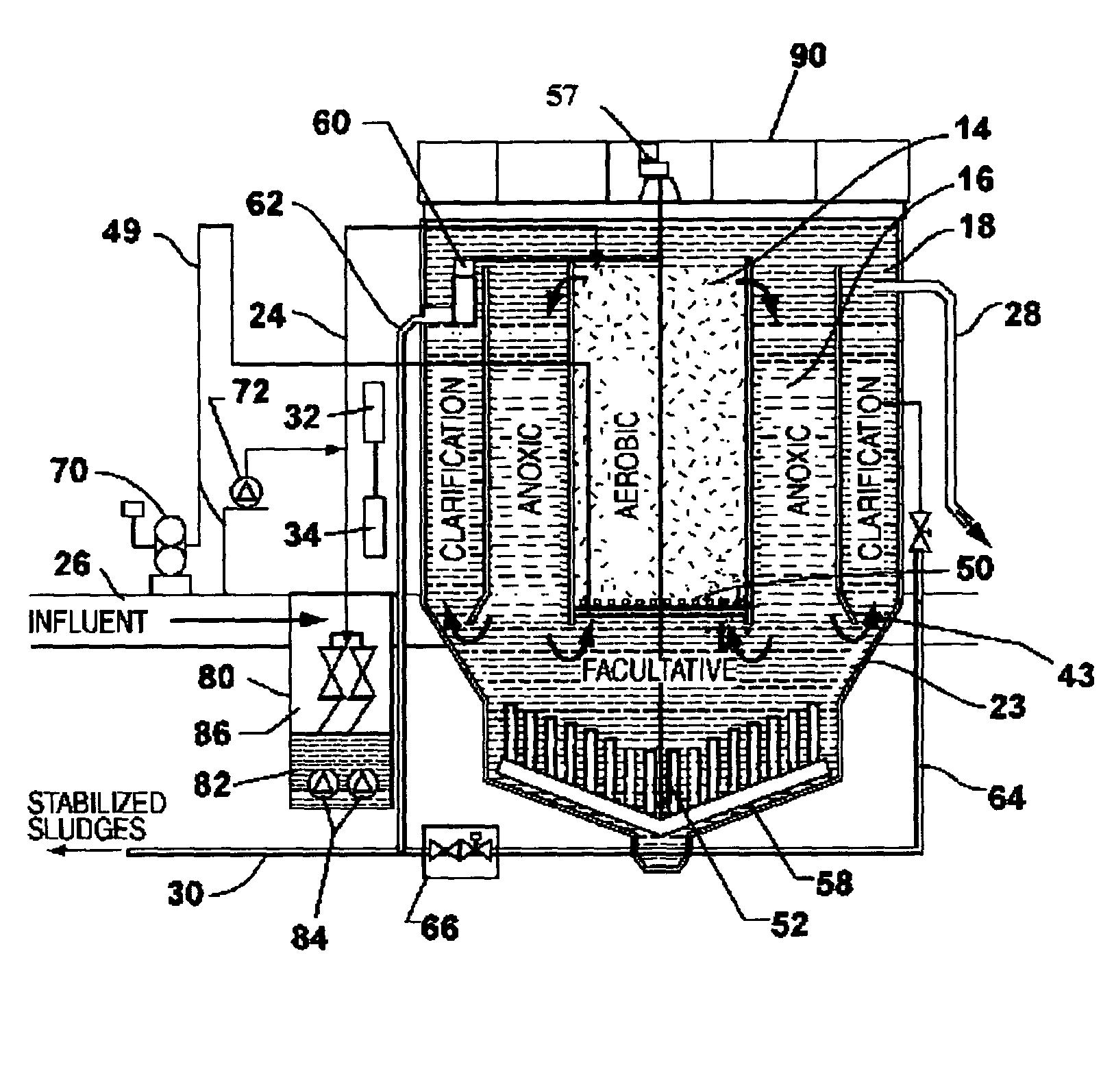
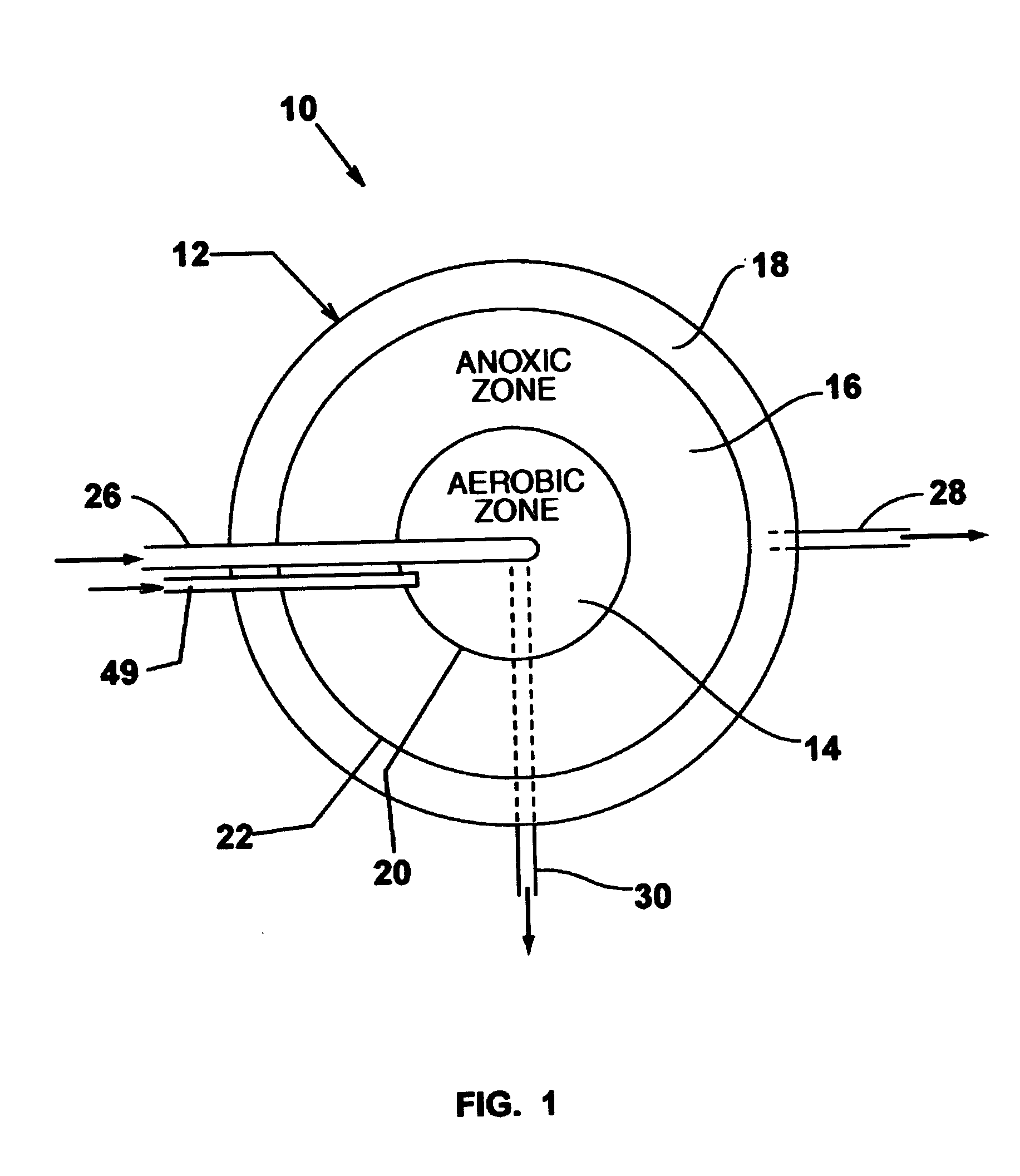
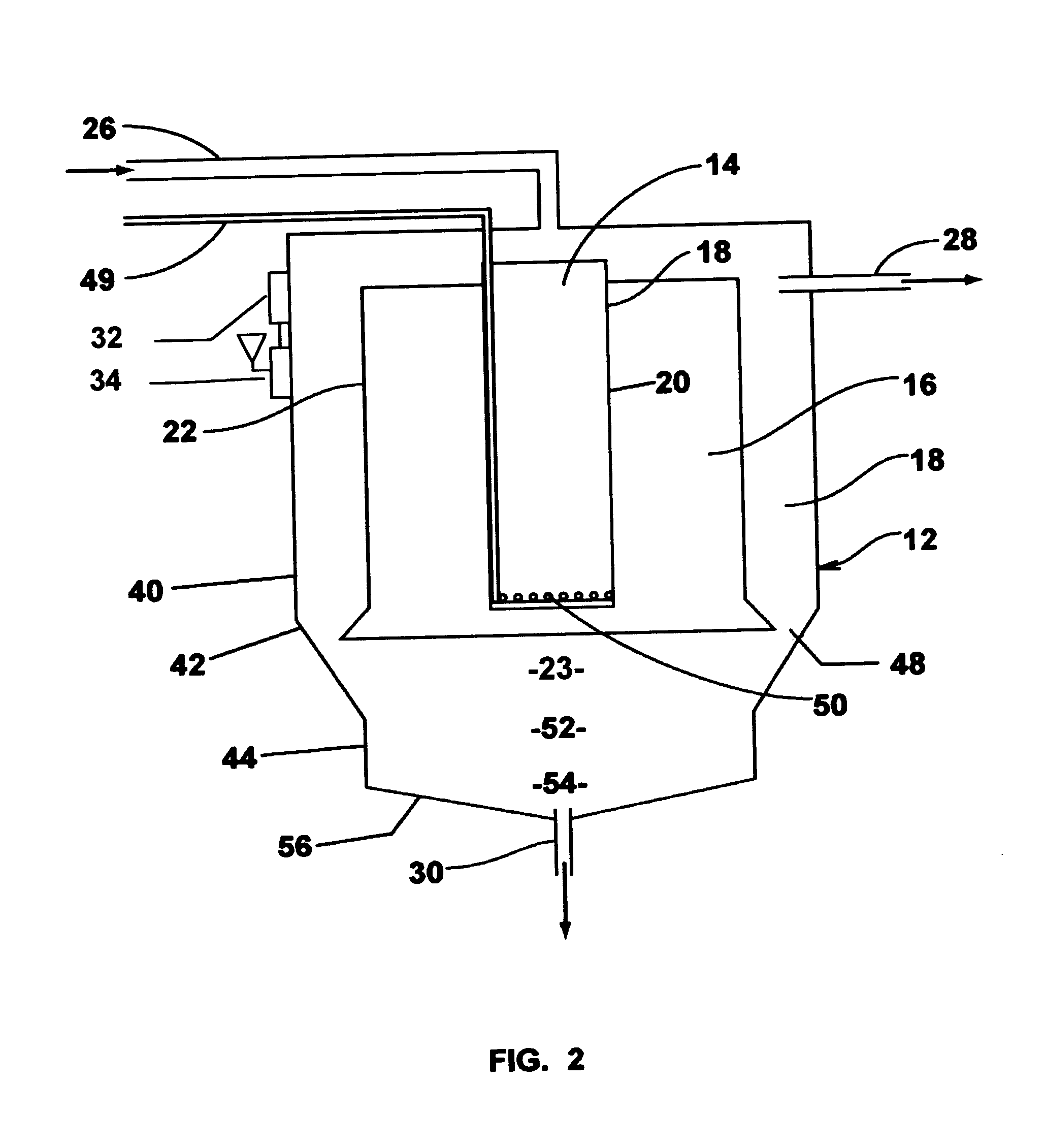
[0028]Thus, it is an object of the instant invention to provide a new and advantageous wastewater treatment system and process that has aerobic, anoxic, facultative, anaerobic, clarification and sludge zones in a single vessel. It is another object of the instant invention to configure the aerobic, anoxic, facultative, anaerobic, clarification and sludge zones of a single vessel wastewater treatment vessel in a new configuration that achieves a more beneficial interaction between those zones to achieve an overall better processing of the wastewater, including removal of undesirable nitrates and phosphorus.

Problems solved by technology

Bulking is particularly undesirable since large quantities of the floc may be associated with final effluent due primarily to it.
Ammonia-nitrogen discharges can result in increased oxygen demand in the receiving stream, as well as depressed dissolved oxygen concentrations.
Ammonia-nitrogen can also be toxic to aquatic organisms.
Nitrite-nitrogen can also be toxic.
Nitrogen and phosphorus discharges can enrich receiving water bodies, resulting in the undesirable growth of algae and other aquatic plants, which is known as eutrophication.
Occasionally, raw wastewater contains oxidized nitrogen species that may inhibit the process.
Even though there is a coupling of anaerobic and aerobic processes, this system is relatively inefficient, with large volumes of fluid and long retention (treatment) times. Inorganics, undesirable nutrients and organic matter escape into the clarifier because not all of the dissolved material is distributed properly.
Another source of inefficiency is the constant dilution of raw material in the anaerobic tank with recycled sludge containing oxidized nitrogen and new influent.
The system operates without a separate clarifier, and is not equipped with a sludge return.
However, the method of U.S. Pat. No. 5,441,634 uses an airlift for transferring dissolved oxygen and movement of MLSS (Mixed liquor and Suspended Solids) into an aeration zone and then still another adjacent aerated zone that does not provide denitrification.
Also by having the anoxic zone as a lower extension of the aeration zone in the prior art Edwards apparatus, there is no continuous controlled and interactive processing between the aeration zone and the anoxic zone whereby the aeration zone breaks down long-carbon chain material and digests fatty acids, in the process producing undesirable nitrates, which can only be removed effectively in a well defined anoxic zone that requires more retention time for denitrification than the aeration zone requires for aerobic treatment.
By having the lower anoxic zone and upper aeration zone vertically contiguous, it is not possible to individually control the important treatment (retention) times of the mixed liquor in the vertically juxtaposed lower anoxic zone and its contiguous upper aeration zone, since narrowing or widening of the aeration zone affects the flow in both zones that are virtually in series.
Such mixing of liquid drawn through the sludge zone for the purpose of promoting an anoxic zone adversely affects the characteristics of the influent before even treatment begins.
Further undesirable intermingling of a portion of the polluted influent occurs with the mixed liquor in the adjacent aerated containment vessel and consequently intermingling occurs with the liquid that enters the annular junction of the clarifier.
Such mixing is not conducive to achieving controlled treatment environments through well-defined treatment environments that are necessary for the required biological processes.
Furthermore the prior art Edwards apparatus lacks controlled retention time related interaction between the aerobic and anoxic zones required for the removal of nitrates and the aerobic, anaerobic and anoxic interactions necessary for phosphorus removal.

Method used


Image

  • Single vessel multi-zone wastewater bio-treatment system
  • Single vessel multi-zone wastewater bio-treatment system
  • Single vessel multi-zone wastewater bio-treatment system

Examples


example 1

ILLUSTRATIVE EXAMPLE 1

[0083]As an illustration of the process in an experimental slaughterhouse wastewater treatment system, the influent of the prior art experimental system around U.S. Pat. No. 5,441,634 includes: water, total suspended solids ranging from 500 to 900 mg / l, Bio-Chemical Oxygen Demand (BOD-5) ranging from 650 to 1000 mg / l, Total Nitrogen ranging from 150 to 200 mg / l and phosphorus ranging from 20 to 40 mg / l.

[0084]The effluent of the prior art process and system of U.S. Pat. No. 5,441,634 treating wastewater from the above illustrative slaughterhouse includes water, suspended solids, nitrogen, and phosphorus.

[0085]The influent of the instant invention for the above slaughterhouse includes the same characteristics as the influent of the prior art Edwards apparatus.

[0086]The effluent of the instant invention treating wastewater from the above slaughterhouse also includes water, suspended solids, nitrogen, and phosphorus.

[0087]Table 1 below illustrates the dramatically ...

example 2

ILLUSTRATIVE EXAMPLE 2

[0089]The relevant influent compositions (liquid and solid) of the prior art pilot wastewater treatment system of U.S. Pat. No. 5,441,634 with a flow of 2870 liters per day, providing treatment for the discharge of a food processing facility producing French fries includes: water, total suspended solids averaging 3300 mg / l, Bio-Chemical Oxygen Demand BOD-5 averaging 2480 mg / l, Total Nitrogen averaging 140 mg / l and phosphorus averaging 44 mg / l.

[0090]The effluent of the prior art system treating wastewater from the above food processing facility includes water, suspended solids, Total Nitrogen and phosphorus.

[0091]For the illustrative experimental pilot food processing wastewater treatment system, the influent of the system of the invention includes the same contents and characteristics as the prior art Edwards system.

[0092]The effluent of the prior art system treating wastewater from the above food processing facility includes water, suspended solids Total Nitro...


PUM

PropertyMeasurementUnit
solids retention timeaaaaaaaaaa
volatileaaaaaaaaaa
liquidaaaaaaaaaa

Abstract

A process for treating wastewater and a system for practicing the process includes: providing a plurality of zones within a single vessel wastewater treatment system; feeding wastewater into the system; maintaining an aerobic zone in the upper central portion of the vessel; feeding air into the aerobic zone for oxygenation and creating an upflow; maintaining an annularly disposed anoxic zone about said aerobic zone; causing the upflow from the aerobic zone to produce a downflow in the anoxic zone; causing at least a portion of the downflow from the anoxic zone to pass into the upflow of the aerobic zone; maintaining an annularly disposed clarification zone about said anoxic zone for clarified liquid, including an upflow; causing at least a portion of the downflow from the anoxic zone to pass into the upflow of the clarification zone; maintaining a facultative transition zone below the upper aerobic, anoxic and clarification zones; maintaining an anaerobic zone below the facultative zone for absorbing solids settled by gravity and synthesizing volatile fatty acids; withdrawing substantially clarified liquid from the upflow of the clarified liquid zone; withdrawing substantially solids from about the bottom of the anaerobic zone; employing the aerobic zone for breaking down carbon chains and oxidizing volatile fatty acids dispersed from the anaerobic zone; interacting the aerobic and anoxic zones for the removal of nitrates; and interacting the aerobic, anaerobic ananoxic zones for the removal of phosphorus.

Description

FIELD OF THE INVENTION[0001]This invention relates to a biological process for treating wastewater, including processing the wastewater to reduce its waste strength to desirable levels for ground water return or better, reducing the total amount of suspended solids in the wastewater to acceptable levels, and removing harmful nitrogen and phosphorous nutrients from the wastewater. The invention also relates to a practical system and method for performing the process.DESCRIPTION OF PRIOR ART[0002]Traditionally, it has been the overall objective of wastewater treatment to prevent the pollution of surface waters by decreasing the amount of suspended solids, decrease the BOD (Biochemical Oxygen Demand normally measured in milligrams per liter and also referred to as BOD-5 signifying measurements over 5 days) in the final effluent and also decrease of the nitrogen and phosphorus compounds in the final effluent. Another important objective was the reduction of pathogens responsible for dis...

Claims


Application Information

Patent Timeline
Patent Type & Authority Patents(United States)
IPC IPC(8): C02F3/00C02FC02F1/44C02F3/30
CPCC02F1/444C02F3/308C02F3/301Y02W10/10
Inventor KASPARIAN, KASPAR A.VERRET, ERIC
Owner KASPARIAN ANN
Learn More