Light emitting diode driver circuit and method

Inactive Publication Date: 2006-03-21
ALLEN DAVID M
View PDF28 Cites 130 Cited by
  • Summary
  • Abstract
  • Description
  • Claims
  • Application Information

AI Technical Summary

Benefits of technology

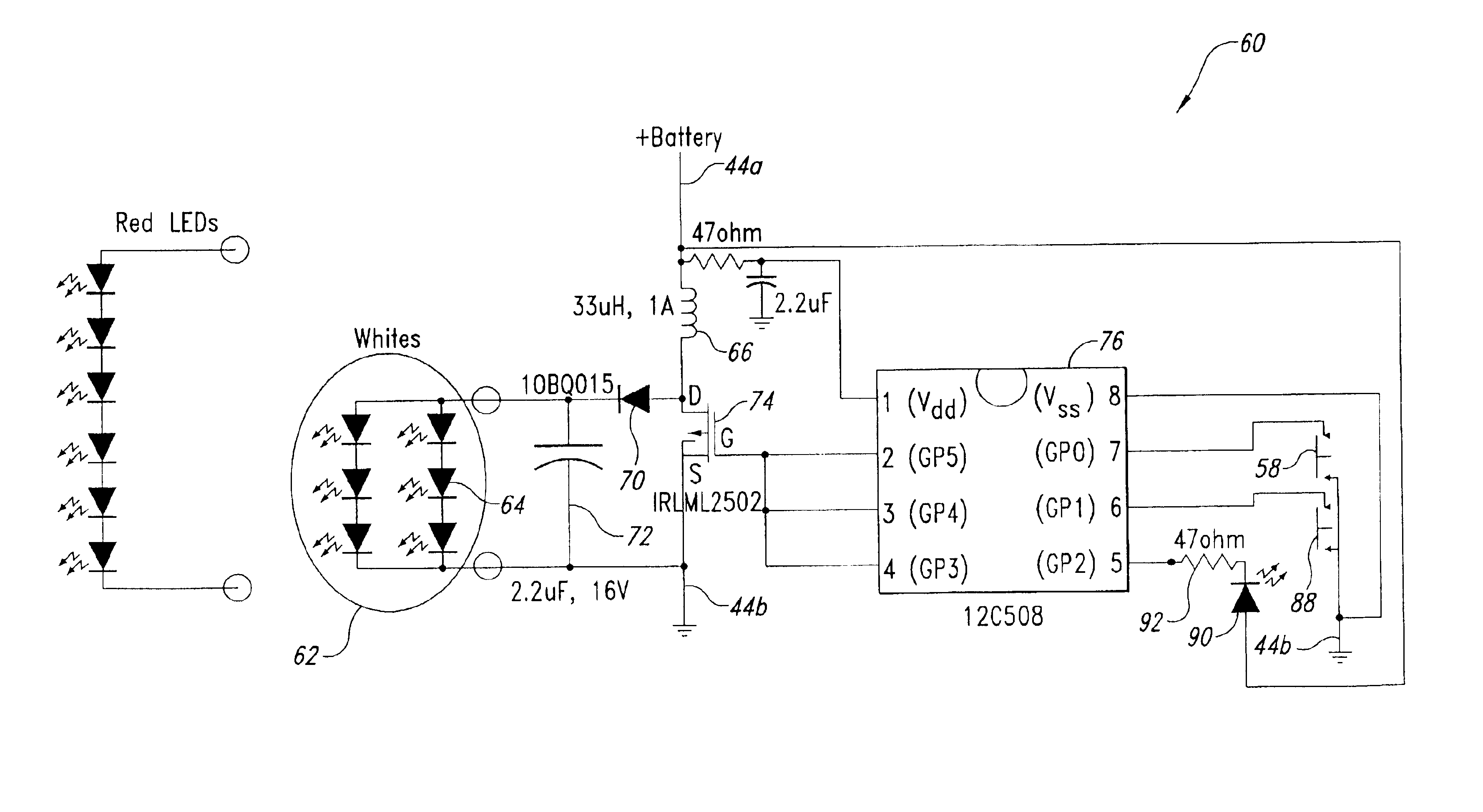
[0010]It is therefore an object of the present invention to provide a light emitting diode driving circuit which conditions the powe

Problems solved by technology

In particular, the capabilities of flashlights of this type are strictly limited by inherent characteristics of the incandescent bulb itself.
Nevertheless, the inherent inefficiency of incandescent bulbs limited the duration of operation of such flashlights to a matter of a few hours or less depending on the number of dry cells provided in the power supply.
In addition, filament bulbs are highly susceptible to mechanical shock, breaking the filament and rendering the flashlight inoperative.
Nevertheless, the circuitry disclosed in Williams et al. for operating the xenon flashtube is expensive, bulky, and only suitable for intermittent operation of the flashtube rather than for providing a constant light output.
Thus, the teachings of the prior art disclosed by Williams et al. is not suitable for remedying the inherent limitations of the incandescent bulb type flashlight technology disclosed by Stone.
As stated above, the fundamental limitations of prior art flashlights related to inherent limitations of incandescent bulb technology, and inherent limitations of electrical circuits for driving other light generating devices such as the xenon flashtube shown in Williams et al.
Unfortunately, such early stage LEDs could not provide significant light output without being driven at very high currents, in which case, the power efficiency of the LED with respect to the quantity of light produced significantly decreased.
Also, LEDs in use during the period in which the Tabor patent application was filed were only capable of producing light in the red part of the visible spectrum.
These two limitations resulted in an LED flashlight only having utility for intermittent operation or continuous illumination ov

Method used


Image

  • Light emitting diode driver circuit and method
  • Light emitting diode driver circuit and method
  • Light emitting diode driver circuit and method

Examples


Embodiment Construction

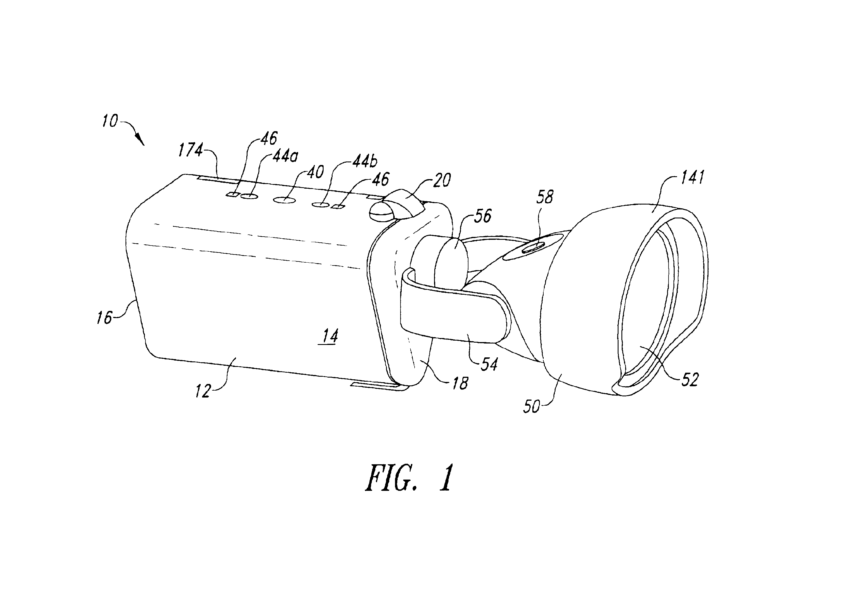
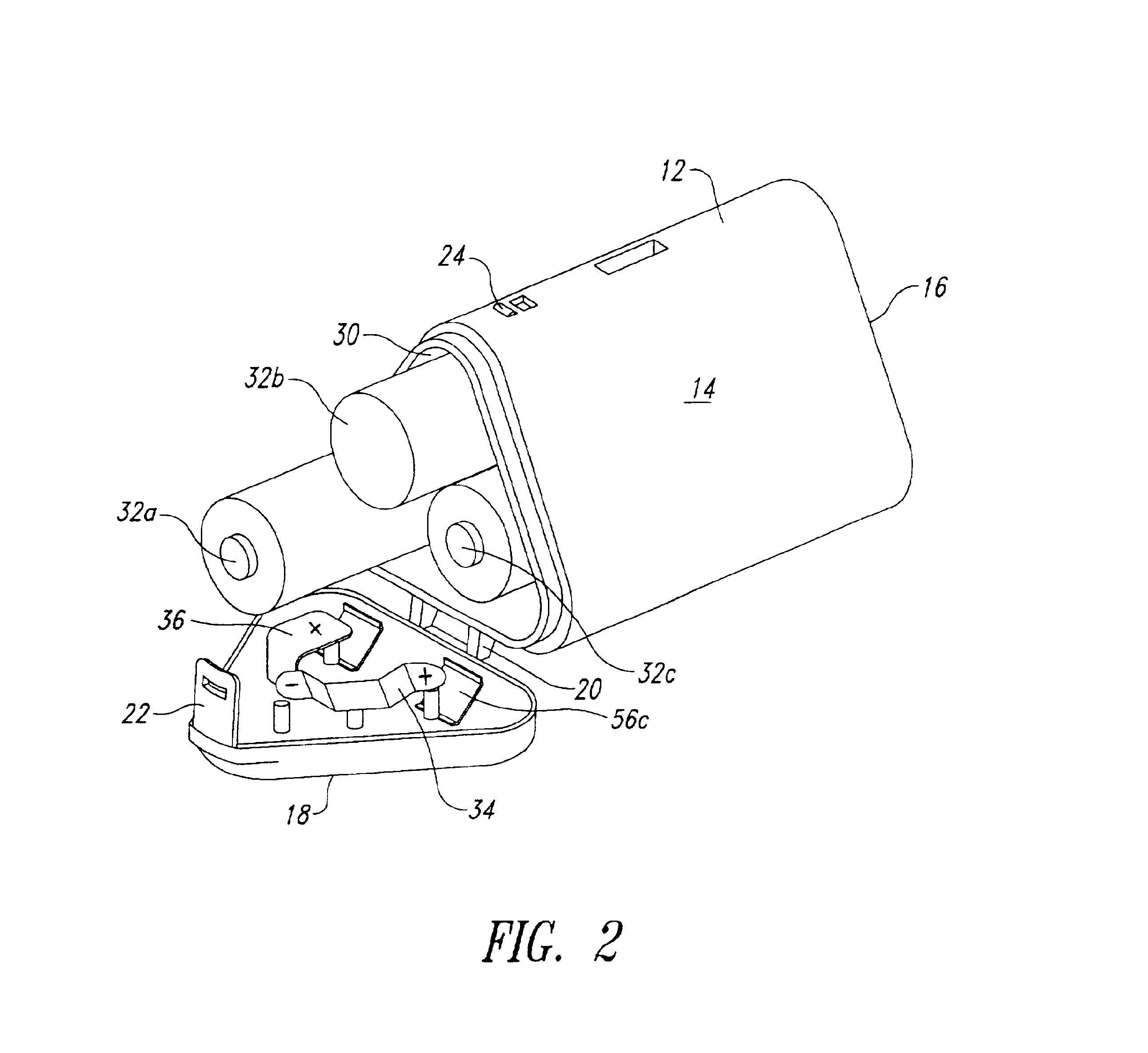
[0027]A convertible flashlight-headlamp, employing a light emitting device driver circuit and method of the present invention, is generally indicated reference numeral 10 in FIG. 1. Mechanical characteristics of the convertible flashlight-headlamp are fully described in U.S. Patent Application entitled “CONVERTIBLE FLASHLIGHT-HEADLAMP” claiming priority from a provisional application of the same title filed on Nov. 16, 2001, Ser. No. 60 / 331,941 and assigned to the assignee of the instant application. The disclosure from that copending application is incorporated herein by reference. For purposes of this disclosure, it is sufficient to state that the convertible flashlight-headlamp 10 has a triangular battery compartment 12 having three sides 14, a fixed end cap 16, and an openable end cap 18 for allowing selective access to the battery compartment. As best seen in FIG. 2, the end cap 18 is pivotable about a hinge 20 and may be secured in a closed position by means of a flexible latc...


PUM


Abstract

A mirco-controller and boost converter circuit provide constant current to light emitting diode array. A micro-controller operatively coupled with a semiconductor switch and the boost converter circuit measure the ability of a DC power supply to change the inductor. Duty cycles of the semiconductor switch are modified according to the measurement so as to supply substantially constant current to the LED array through an inductor regardless of actual battery voltage.

Description

CROSS-REFERENCE TO RELATED APPLICATION[0001]This application claims priority from co-pending, U.S. Provisional Application No. 60 / 331,941 titled CONVERTIBLE FLASHLIGHT-HEADLAMP filed on Nov. 16, 2001.BACKGROUND OF THE INVENTION[0002]1. Field of the Invention[0003]The invention generally relates to portable illumination devices. More specifically, the invention relates to personal, handheld flashlights having a self-contained direct current power supply and one or more light emitting diodes as a light source.[0004]2. Description of the Related Art[0005]Technology relating to handheld flashlights incorporating a direct current power supply in the form of replaceable batteries and low voltage, incandescent bulbs achieved a technological plateau in the 1970's. Advances in the state of the art typically related to methods of packaging the batteries and bulbs, and reflector designs. In particular, the capabilities of flashlights of this type are strictly limited by inherent characteristic...

Claims


Application Information

Patent Timeline
IPC IPC(8): H03K3/42
CPCH02M3/156H05B33/0845H05B33/0815H05B33/0803H02J1/04H05B45/10H05B45/3577H05B45/38
Inventor KUHLMANN, KURT A.ALLEN, DAVID M.
Owner ALLEN DAVID M
Why Eureka
Try Eureka