Extremely high-speed switchmode DC-DC converters

a converter and switchmode technology, applied in the direction of electric variable regulation, process and machine control, instruments, etc., can solve the problems of inefficient dc at lower drive levels, extreme high 2 mhz switching frequency, and tendency to degrade linearity, so as to improve the efficiency and battery saving capabilities of wireless devices

Inactive Publication Date: 2006-04-11
MURATA MFG CO LTD +1
View PDF5 Cites 41 Cited by
  • Summary
  • Abstract
  • Description
  • Claims
  • Application Information

AI Technical Summary

Benefits of technology

[0014]Switchmode DC—DC power converters employing one or more non-Silicon-based switching transistors and a Silicon-based (e.g. CMOS) controller are disclosed. The non-Silicon-based switching transistors may comprise, but are not necessarily limited to, III-V compound semiconductor devices such as gallium arsenide (GaAs) metal-semiconductor field effect transistors (MESFETs) or heterostructure FETs such as high electron mobility tra

Problems solved by technology

However, because smaller RF input levels (i.e. lower PA drive levels) require less DC power for the same gain, the PA becomes inefficient at lower drive levels.
When applied to a conventional linear amplifier this technique tends to degrade linearity, as it varies the bias of the active devices.
Unfortunately, most DC—DC power converters operate with a switching frequency below 1 MHz, and a 2 MHz switching frequency is considered to be extremely high.
This is undesirable from both cost and integration compatibility points of view.
Any use of bipolar transistors on a chip forces the use of a more expensive process.
How to control and drive these huge transistors is an extremely important issue.
Due to the large gate capacitances of the switching transistors 12 and 14, however, the required size of the drivers could be prohibitively large and in many instances, irrespective of size, simply unable to tr

Method used


Image

  • Extremely high-speed switchmode DC-DC converters
  • Extremely high-speed switchmode DC-DC converters
  • Extremely high-speed switchmode DC-DC converters

Examples


Embodiment Construction

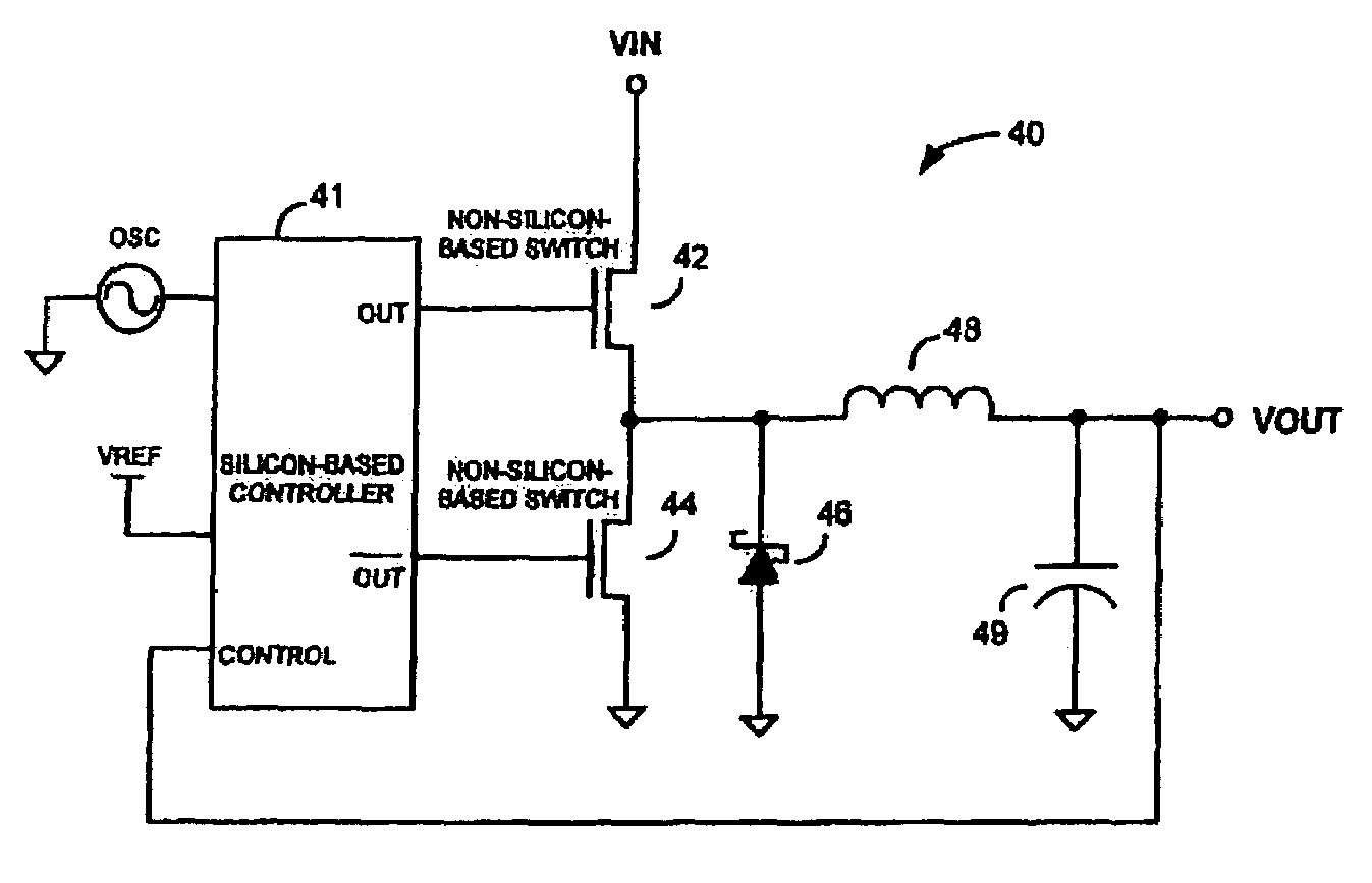
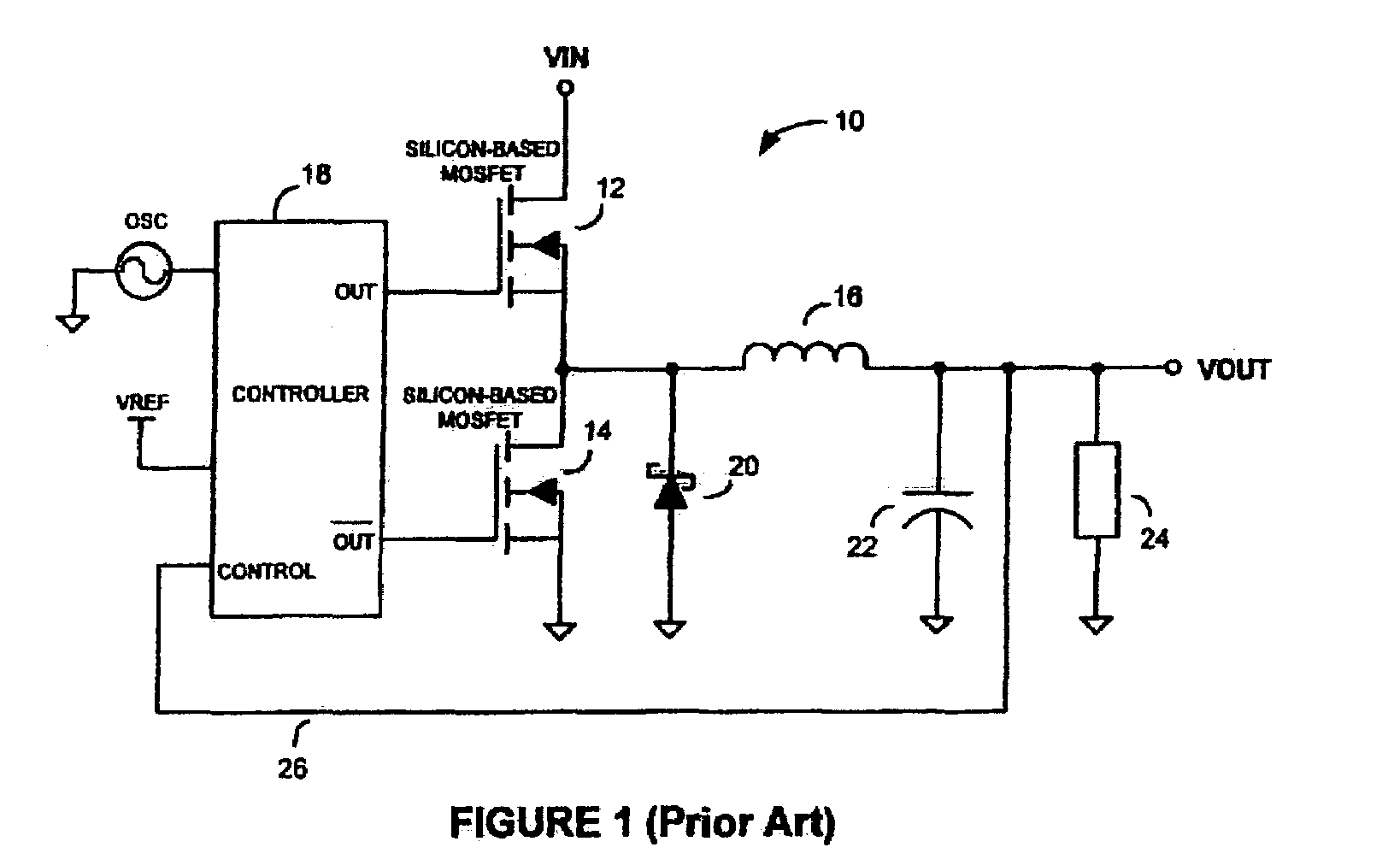
[0029]Referring to FIG. 4, there is shown a schematic diagram of an exemplary synchronous DC—DC power converter 40, according to an embodiment of the present invention. Converter 40 comprises a Silicon-based (e.g. CMOS) controller 41, non-Silicon-based switching transistors 42 and 44, a Schottky diode 46, an inductor 48, and a capacitor 49. FIG. 5 shows a schematic diagram of an alternative topology of a DC—DC converter 50, according to an alternative embodiment of the present invention. Converter 50 comprises a Silicon-based (e.g. CMOS) controller 52, a non-Silicon-based switching transistor 54, a diode 55, an inductor 56, and a capacitor 58. Unlike prior art power converters (e.g. the power converter 10 in FIG. 1), converters 40 and 50 are capable of following wide-bandwidth envelope variations of wide-bandwidth technologies such as, for example, EDGE and UMTS. Accordingly, as described in more detail below, the power converters of the present invention may be used to, for example...


PUM


Abstract

Switchmode DC—DC power converters using one or more non-Silicon-based switching transistors and a Silicon-based (e.g. CMOS) controller are disclosed. The non-Silicon-based switching transistors may comprise, but are not necessarily limited to, III-V compound semiconductor devices such as gallium arsenide (GaAs) metal-semiconductor field effect transistors (MESFETS) or heterostructure FETs such as high electron mobility transistors (HEMTs). According to an embodiment of the invention, the low figure of merit (FoM), τFET, of the non-Silicon-based switching transistors allows the converters of the present invention to be employed in envelope tracking amplifier circuits of wireless devices designed for high-bandwidth technologies such as, for example, EDGE and UMTS, thereby improving the efficiency and battery saving capabilities of the wireless devices.

Description

FIELD OF THE INVENTION[0001]The present invention relates generally to power conversion. More particularly, the present invention relates to extremely high-speed switchmode DC—DC converters.BACKGROUND OF THE INVENTION[0002]Switchmode DC—DC power converters are commonly used in electronic devices. They operate by converting the voltage of an available voltage source to a voltage that complies with the voltage requirements of one or more components of the device. More particularly, switchmode DC—DC power converters operate to convert a direct current (DC) input voltage to a DC output voltage that is higher (boost converter) or lower (buck converter) than the DC input voltage. A common application of a buck converter is the conversion of an available voltage source in a personal computer (PC) to a voltage compatible with the voltage source requirements of devices and integrated circuits (e.g. the central processing unit (CPU)) on the motherboard of the PC.[0003]A conventional DC—DC buc...

Claims


Application Information

Patent Timeline
IPC IPC(8): G05F1/613H02M3/155
CPCH02M3/155H03F1/0227H02M3/158Y02B70/1483Y02B70/10
Inventor MCCUNE, JR., EARL WILLIAM
Owner MURATA MFG CO LTD
Why Eureka
Try Eureka