
Implantable sensor

a sensor and sensor technology, applied in the field of implantable sensors, can solve the problems of increased risk of heart disease, increased risk of end-stage renal disease, and increased risk of hypoglycemia, and achieve the effects of minimizing the thickness of the formed thrombus layer, avoiding the occurrence of fibrotic reactions, and avoiding fibrotic reactions

Inactive Publication Date: 2006-04-25
SILVER JAMES H
View PDF38 Cites 455 Cited by
  • Summary
  • Abstract
  • Description
  • Claims
  • Application Information

AI Technical Summary

Benefits of technology

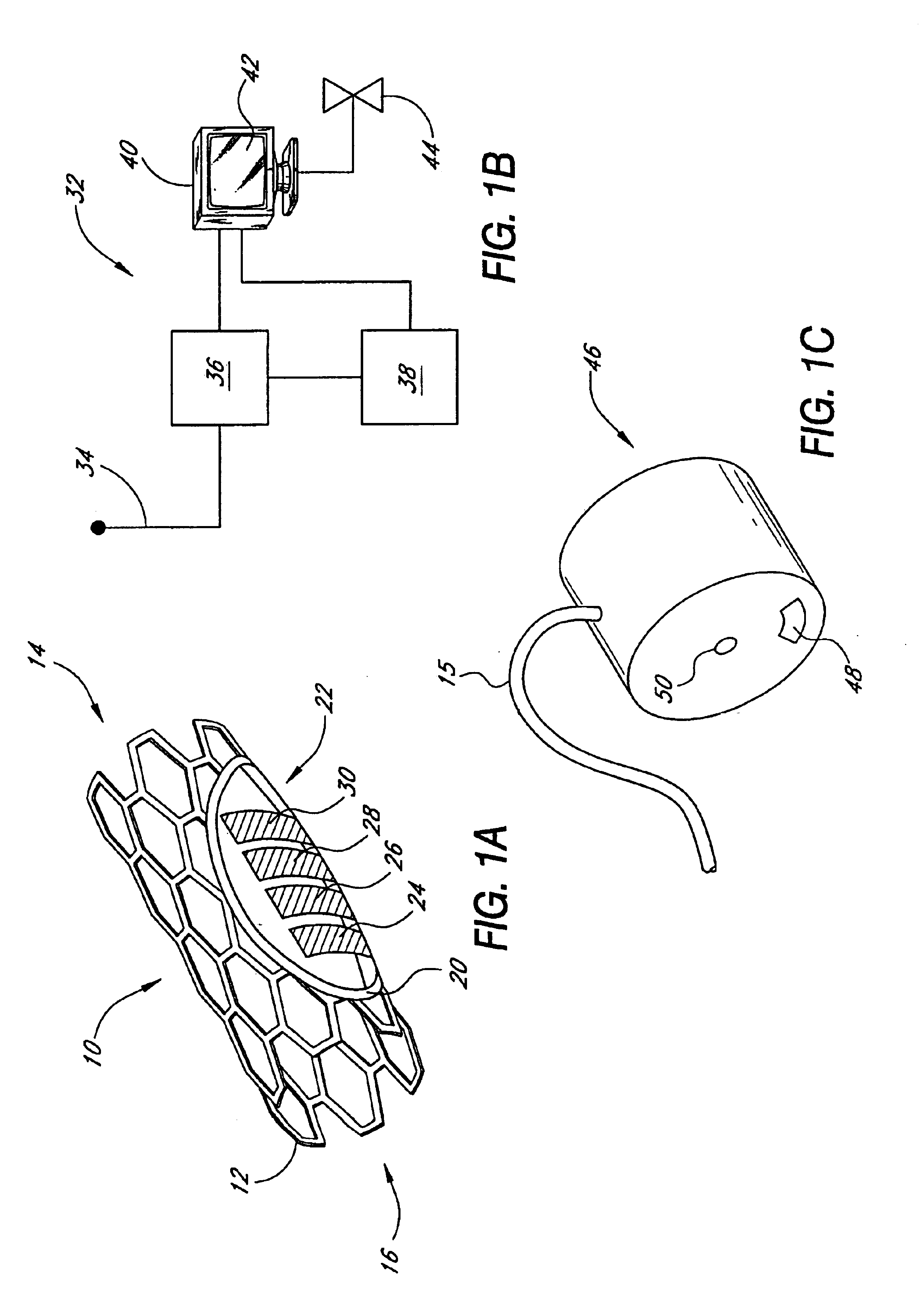
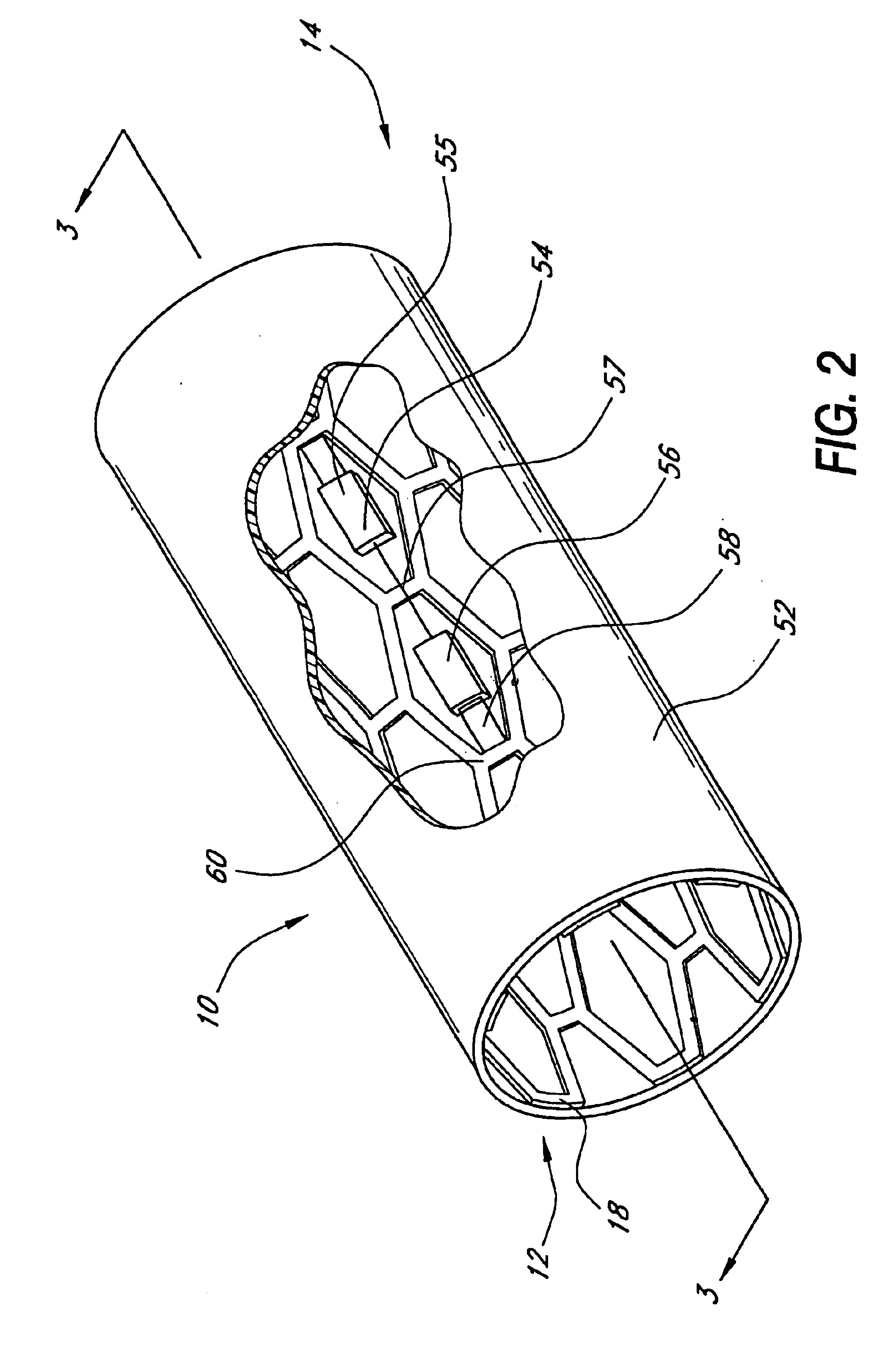
"The present invention relates to the use of sensors to monitor the concentration of a chemical species in bodily fluids, specifically glucose levels in a body vessel. The invention provides a novel sensor configuration that minimizes the thickness of the formed thrombus layer and prevents tissue deposition or encapsulation due to potential fibrotic reactions. The sensor is placed at the apex of the luminal surface of a streamlined housing, which is delivered to the patient's vascular system transluminally via a catheter. The sensor has a sensing surface that is exposed to the exterior of the housing and is positioned on the radially inwardly most portion of the luminal side of the housing. The invention also provides a method of prolonging the useful life of the sensor and an implantable sensor for sensing the presence of an analyte in a vessel."

Problems solved by technology

The long-term consequences of diabetes include increased risk of heart disease, blindness, end-stage renal disease, and non-healing ulcers in the extremities.
Unfortunately, a major difficulty encountered during the trial was that intensive treatment also resulted in a higher incidence of low blood glucose levels (hypoglycemia), which was severe enough to result in coma or death, as compared to patients under conventional medical management.
The major drawback to self-monitoring of glucose is that it is discontinuous and therefore the number of glucose measurements performed is dependent on the motivation of the patient.
There are two main disadvantages to these existing options.
First, sampling even a minimal amount of blood multiple times per day is associated with risks of infection, nerve and tissue damage, and discomfort to the patients.
These highly overlapping, weakly absorbing bands were initially thought to be too complex for interpretation and too weak for practical application.
However, to date these devices are not particularly accurate even in the normal physiological range.
The temperature sensitivity of water absorption bands in the glucose-measuring region can be a significant source of error in clinical assays.
In addition, the devices can also be affected by individual variations between patients at the measurement site.
Skin location, temperature and tissue structure may affect the results, and decrease the accuracy of the reading.
However, factors relating to diet and exercise can affect glucose levels in these fluids.
The lag time between blood and excreted fluid glucose concentrations can be large enough to render such measurements inaccurate.
Failure to respond can result in loss of consciousness and in extreme cases convulsive seizures.
At present, none of them meets the selectivity requirements to sense and accurately measure glucose in real physiological fluids.
Despite the foregoing and other efforts in the art, a suitable continuous in dwelling glucose sensor has not yet been developed.
However, due to the risks of thrombosis and embolization, the majority of investigators have focused on subcutaneous implantation.
A major drawback to subcutaneous implantation is the body's defense against foreign objects: the “foreign-body response”.
If the object is a blood glucose sensor, it will no longer be in intimate contact with body fluids, and the signal will drift and stability will be lost.

Method used


Image

  • Implantable sensor
  • Implantable sensor
  • Implantable sensor

Examples


Embodiment Construction

[0066]In accordance with the present invention, an intraluminal blood glucose sensor is provided on a support structure such as a modified stent of the type implanted following percutaneous transluminal coronary angioplasty (PTCA) for the treatment of atherosclerosis. Atherosclerosis is the build-up of fatty deposits or plaque on the inner walls of a patient's arteries. These lesions decrease the effective size of the artery lumen and limit blood flow through the artery, prospectively causing a myocardial infarction or heart attack if the lesions occur in coronary arteries that supply oxygenated blood to the heart muscles. In the angioplasty procedure, a guide wire is inserted into the femoral artery and is passed through the aorta into the diseased coronary artery. A catheter having a balloon attached to its distal end is advanced along the guide wire to a point where the stenotic lesions limit blood flow through the coronary artery. The balloon is then inflated, compressing the le...


PUM


Abstract

A sensor is disclosed, for implantation within a blood vessel to monitor an analyte in blood. In one embodiment, the analyte is glucose. A signal indicative of glucose level is transmitted to an external receiver. The signal may also be used to drive an internal or externally worn insulin pump. Methods are also disclosed.

Description

[0001]This is a continuation-in-part of U.S. patent application Ser. No. 09 / 571,702, filed May 15, 2000, now U.S. Pat. No. 6,442,413 issued on Aug. 27, 2002.BACKGROUND OF THE INVENTION[0002]1. Field of the Invention[0003]2. Description of the Related Art[0004]The present invention generally relates to the use of sensors to monitor the concentration of a chemical species in bodily fluids. More specifically, the present invention relates to the use of sensors to monitor glucose levels, and / or other parameters in a fluid, including flow rate within a lumen of an endoluminal implant such as a stent or other type of endovascular conduit.[0005]Diabetes mellitus is a serious medical condition affecting approximately 10.5 million Americans, in which the patient is not able to maintain blood glucose levels within the normal range (normoglycemia). Approximately 10% of these patients have insulin-dependent diabetes mellitus (Type I diabetes, IDDM), and the remaining 90% have non-insulin-depend...

Claims


Application Information

Patent Timeline
Patent Type & Authority Patents(United States)
IPC IPC(8): A61B5/00
CPCA61B5/0031A61B5/14865A61B5/6862A61B5/6876A61B2560/0219
Inventor SILVER, JAMES H.
Owner SILVER JAMES H
Learn More