Exposure apparatus and exposure method

a technology which is applied in the field of exposure apparatus and exposure method, can solve the problems of color aberration correction difficulty, sharp drop of reflectance, and oxidation of antireflection coatings formed on the lens surface, and achieve the effect of maintaining the initial performan

Inactive Publication Date: 2006-05-23
NIKON CORP
View PDF18 Cites 39 Cited by
  • Summary
  • Abstract
  • Description
  • Claims
  • Application Information

AI Technical Summary

Benefits of technology

[0014]The present invention was made in consideration of this point and has as its object the realization of an exposure apparatus and exposure method able to maintain the reflectance of the reflection mirrors or the transmittance of the lenses included in an optical system in a good state and to maintain the initial performance over a long period even when using vacuum ultraviolet light as the exposure light.
[0015]Further, it enables the pickup of heat by the optical elements (mirrors, lenses, etc.) due to the exposure light to be prevented and stable optical performance to be exhibited over a long period.

Problems solved by technology

Therefore, in a refraction optical system, correction of color aberration is difficult.
In this wavelength region, as a metal layer having a high reflectance, aluminum etc. may be mentioned, but as explained above, there is the problem that if the gas-purged light path has even a little oxygen or water vapor remaining it in, the photochemical reaction caused by the irradiation of the vacuum ultraviolet light will cause this aluminum layer to be oxidized resulting in its reflectance sharply dropping.
Oxidation is not a problem that occurs only for mirrors including aluminum layers and is a problem which similarly occurs even if using another metal.
Further, not only reflection mirrors and flat mirrors, but also antireflection coatings formed on the lens surfaces oxidize by the photochemical reaction with residual oxygen or water vapor and fall in transmittance.
In particular, regarding water vapor, moisture adsorbed at the barrels or lens holding mechanisms forming the optical system continues to disassociate slowly over a long time, so it is difficult to suppress the concentration to not more than 1 ppm.
If the reflectance of the reflection mirrors or the transmittance of the antireflection coatings of the lens surfaces falls, the exposure energy reaching the wafer or other substrate to be exposed falls, so there is the problem that the processing ability of the exposure apparatus falls and the initial performance of the exposure apparatus can no longer be maintained.
Further, even if the above oxidation does not occur, it is not possible to produce mirrors with that high a reflectance in the vacuum ultraviolet region.
Therefore, part of the exposure light is absorbed by the mirrors and make the mirrors pick up heat.
As a result, the mirrors are liable to deform due to heat expansion.

Method used


Image

  • Exposure apparatus and exposure method
  • Exposure apparatus and exposure method
  • Exposure apparatus and exposure method

Examples


first embodiment

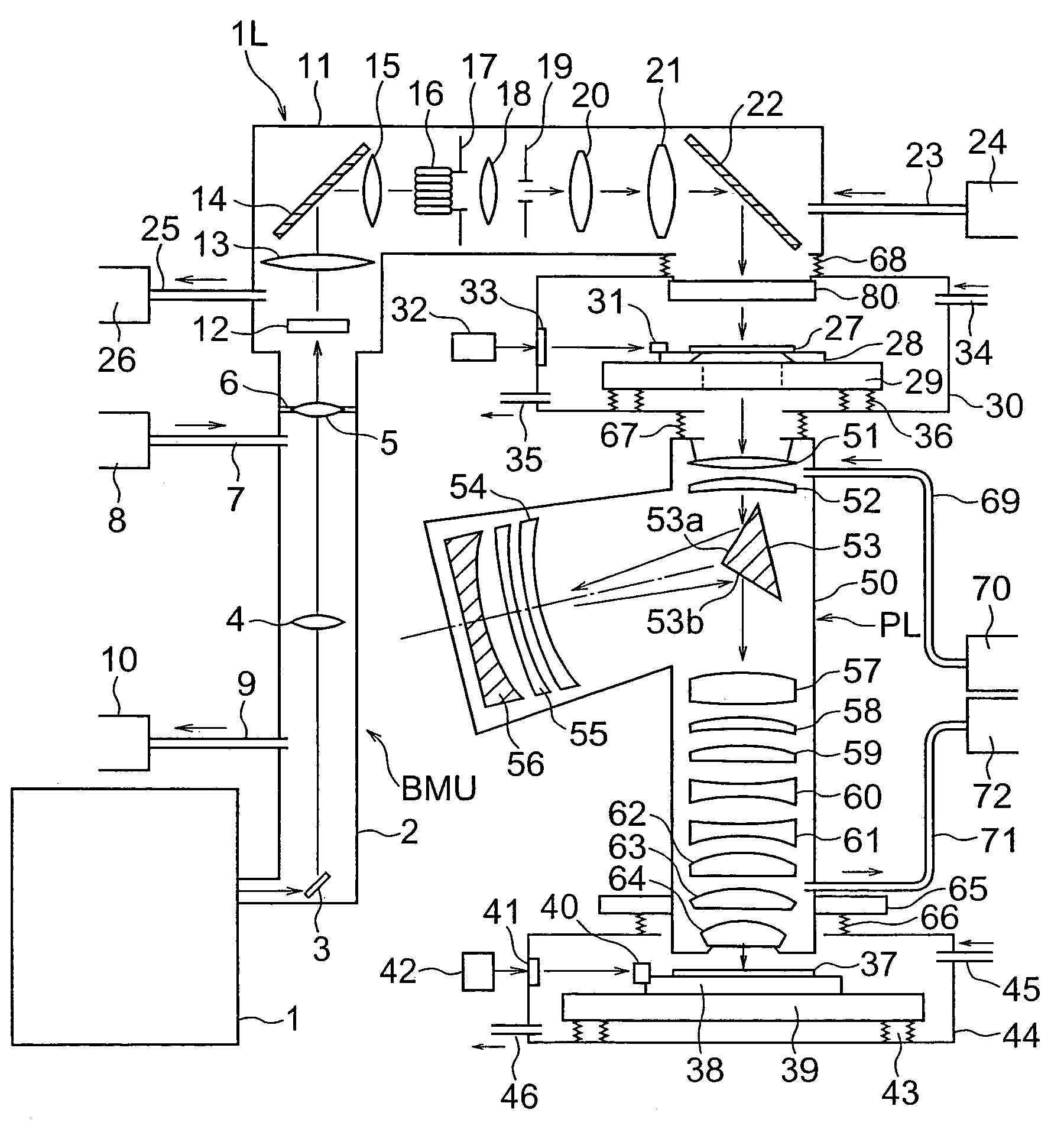
[0058]Below, embodiments of the present invention will be explained using the drawings. FIG. 1 is a view of the general configuration of an exposure apparatus according to the present invention. This exposure apparatus is a step-and-scan type (scan type) projection exposure apparatus. A light beam emitted from a wavelength 157 nm fluorine laser (F2 laser), wavelength 146 nm krypton dimer laser (Kr2 excimer laser), wavelength 126 nm argon dimer laser (Ar2 excimer laser), or other vacuum ultraviolet region light source 1 is irradiated through a beam matching unit (however, in the broad sense, part of an illumination optical system) BMU and an illumination optical system IL to a mask 27, whereby patterns on the mask 27 are projected by a projection optical system PL on a wafer 37.

[0059]The beam matching unit BMU is comprised of a bending mirror 3 and relay lenses 4, 5 housed in a BMU chamber 2. The illumination light beam is guided to a diffraction optical element 12 housed in an illum...

second embodiment

[0063]Note that the above beam matching unit BMU and illumination optical system IL are housed in the BMU chamber 2 and illumination system chamber 11 provided with the highly air-tight partition walls, so are isolated from the outside space. The BMU chamber 2 and illumination system chamber 11 are separated in inside space (light path space) by the relay lens 5 and its support member 6. The aperture of the mask 27 side end of the illumination system chamber 11 is sealed air-tightly by a transparent plate 80. The relay lens 5 and support member 6 are configured in the same way as a seal member 191 and support member 192 of the later explained

[0064]The light beam passing through the mask 27 is imaged by the projection optical system PL housed in the barrel 50 and forms images of the patterns of the mask 27 on the wafer 37. The light beam emitted from the mask 27, in the projection optical system 50, passes through the lenses 51, 52 and is reflected at an upper reflection surface 53a ...

third embodiment

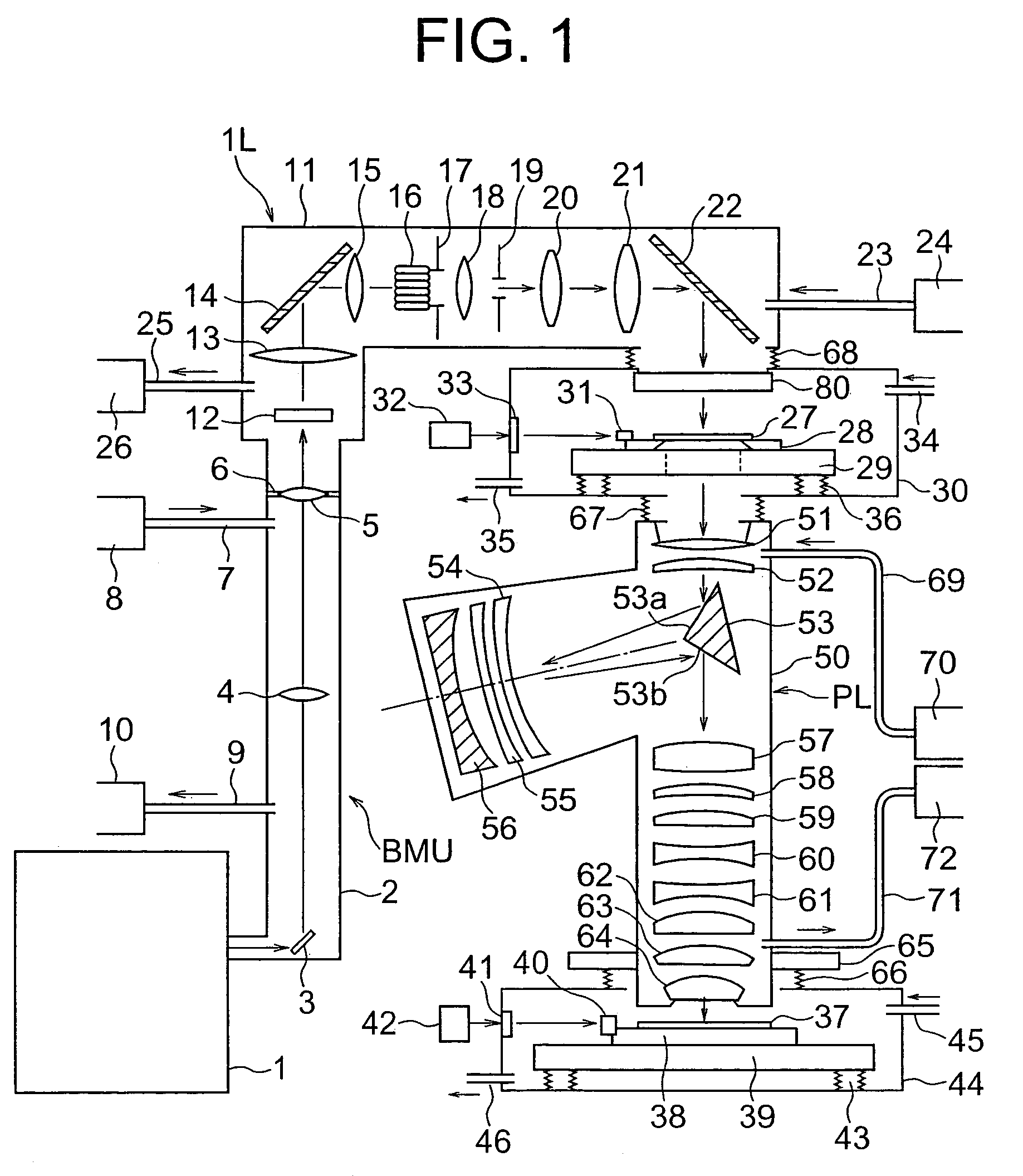
[0098]Note that, in this third embodiment, a single type of gas is fed to the barrels 100, 101 of the projection optical system PL, so the gas feeders 162, 165, 168, 170 may also be combined into a single feeder.

[0099]Further, in this third embodiment, the low absorption gas was made helium, but when there is no need to positively cool the mirrors 113, 117, it may be nitrogen or another rare gas as well. Further, as in the first and second embodiments, it is possible to use a gas comprised of nitrogen or a rare gas in which a predetermined concentration of hydrogen is mixed so as to prevent oxidation of the mirrors 113, 117 better. Note that, the gas blowing mechanism in the third embodiment may also be applied to the first and second embodiments.

[0100]Further, as in this third embodiment, the method of locally blowing on the mirrors 113, 117 a low absorption gas to prevent their oxidation may also be applied to the lenses of the projection optical system PL and the optical elements...


PUM

PropertyMeasurementUnit
wavelength bandaaaaaaaaaa
reflectanceaaaaaaaaaa

Abstract

An exposure apparatus able to maintain reflectances of mirrors and transmittances of lenses and to maintain initial performance over a long period by using exposure light of a wavelength of the vacuum ultraviolet region to illuminate a mask and transfer images of patterns on the mask to a substrate, provided with a gas feed unit for supplying a light path space through which the exposure light passes with a gas mainly comprised of an inert gas or rare gas and introducing a predetermined concentration of hydrogen into the gas fed to at least part of the light path space.

Description

[0001]This is a Continuation of International Application No. PCT / JP03 / 07398 filed Jun. 11, 2003, which claims the benefit of Japanese Patent Application No. 2002-169496 filed Jun. 11, 2002. The entire disclosure of the prior application is hereby incorporated by reference herein in its entirety.TECHNICAL FIELD[0002]The present invention relates to an exposure apparatus and exposure method used when producing a semiconductor integrated circuit, liquid crystal display, thin film magnetic head, or other microdevice or a photomask etc. using photolithography.BACKGROUND ART[0003]When forming fine patterns of a semiconductor integrated circuit, liquid crystal display, or other electronic device, the method of reducing and transferring by exposure the patterns of a photomask (also called a “reticle”) enlarging the patterns to be transferred 4- to 5-fold or so to a wafer or other substrate to be exposed using a projection exposure apparatus has been used.[0004]The projection exposure appar...

Claims


Application Information

Patent Timeline
Patent Type & Authority Patents(United States)
IPC IPC(8): G03B27/53G03F7/20
CPCG03F7/70808G03F7/70933G03F7/70825
Inventor OWA, SOICHISHIRAISHI, NAOMASAAOKI, TAKASHI
Owner NIKON CORP
Why Eureka
Try Eureka